Direct 3D Printer Control - Part 1
/This is the first of a series of posts about how to directly generate GCode for your 3D printer. In the last article I demonstrated how to turn a mesh into GCode with about 12 lines of code. That's fine if you want to experiment with meshes. But what if you want to control the printer yourself? The Gradientspace Slicer is designed to make this easy at several different levels.
To start, you'll need the geometry3Sharp, gsGCode, and gsSlicer libraries. If you check out the gsSlicerApps repository, this is all set up for you, and you'll find the sample code below in the GeneratedPathsDemo Visual Studio project.
Ok, here is the basic harness we will use for all our examples. This is largely boilerplate code, however you will need to use the right Settings object for your printer (assuming it's explicitly supported, otherwise you can try RepRapSettings, it will work with many printers). And you might need to modify some fields in the Settings. But otherwise you don't need to change this code, we'll just fill in the middle bit
// You'll need the Settings object suitable for your printer
RepRapSettings settings = new RepRapSettings();
// you can customize the settings below
settings.ExtruderTempC = 200;

// we want to accumulate the gcode commands to a GCodeFile
var gcode_accumulator = new GCodeFileAccumulator();
var builder = new GCodeBuilder(gcode_accumulator);

// the Compiler turns 2D/3D paths into GCode commands
SingleMaterialFFFCompiler compiler = new SingleMaterialFFFCompiler(
    builder, settings, RepRapAssembler.Factory);

compiler.Begin();

// (THIS IS WHERE WE ADD TOOLPATHS)

compiler.End();

// this bit writes out the GCodeFile to a .gcode file
GCodeFile gcode = gcode_accumulator.File;
using (StreamWriter w = new StreamWriter("c:\\demo\\generated.gcode")) {
    StandardGCodeWriter writer = new StandardGCodeWriter();
    writer.WriteFile(gcode, w);
}
Before we continue, a bit about the gsSlicer/gsGCode architecture and terminology. The basic idea here is that most of the time we want to be working at a higher level then GCode commands. We want to be able to define the geometric paths the print head will move along at the level of 2D/3D polygons and polylines. These are called Toolpaths. We will build up ToolpathSet objects, which are just lists of IToolpath instances, and then pass these to a Compiler that will sort out how to turn them into GCode.
The Compiler level is intended to support other outputs besides gcode, like laser paths for an SLS machine. The SingleMaterialFFFCompiler is suitable for use with 3-axis single-material FDM/FFF 3D printers. Internally, this Compiler creates an IDepositionAssembler instance, which currently is always a subclass of BaseDepositionAssembler. The Assembler provides lower-level commands like MoveTo, ExtrudeTo, and so on, which map more directly to actual GCode commands. The GCodeBuilder we created above is used by the Assembler to emit GCodeLine objects into a GCodeFile.
If that was confusing, here's a diagram. The basic idea is that, you can pass Toolpaths to the Compiler, and it will look at them and decide how to best turn them into lower-level commands that the Assembler will be able to translate into machine-specific GCode. This is what SingleMaterialFFFPrintGenerator does internally. That class takes the mesh slices and figures out how to fill them with Toolpaths, which it then compiles. But we can also generate Toolpaths directly with code, and send them to the Compiler. Or, we could skip over the Compiler entirely, and use the Assembler. You can even use the GCodeBuilder interface, if you really want to control every aspect of the printer (or program some other kind of machine).

The Compiler/Assembler terminology here is borrowed from programming language compilers. I think about it the same way. GCode is very analogous to CPU assembly language - both are lists of very simple structured text commands, (mostly) evaluated in-order. If we push this analogy, we could think of Toolpaths as the "C" of 3D printers, and Meshes are perhaps a high-level scripting language.
In this post we'll focus on the Toolpath level. To simplify the creation of Toolpaths we'll use a helper class called ToolpathSetBuilder. This class knows how to transform basic geometry3Sharp classes like Polygon2d into ToolpathSet objects, which are a bit more complicated. Here is a function that compiles a vertical stack of circles, to make a tube. You would call this function in the "// THIS IS WHERE WE ADD TOOLPATHS" space above.
static void generate_stacked_polygon(SingleMaterialFFFCompiler compiler,
    SingleMaterialFFFSettings settings)
{
    int NLayers = 10;
    for (int layer_i = 0; layer_i < NLayers; ++layer_i) {
        // create data structures for organizing this layer
        ToolpathSetBuilder layer_builder = new ToolpathSetBuilder();
        SequentialScheduler2d scheduler = new SequentialScheduler2d(layer_builder, settings);
        if (layer_i == 0)  // go slower on first layer
            scheduler.SpeedHint = SchedulerSpeedHint.Careful;

        // initialize and layer-up
        layer_builder.Initialize(compiler.NozzlePosition);
        layer_builder.AppendZChange(settings.LayerHeightMM, settings.ZTravelSpeed);

        // schedule a circle
        FillPolygon2d circle_poly = new FillPolygon2d(Polygon2d.MakeCircle(25.0f, 64));
        circle_poly.TypeFlags = FillTypeFlags.OuterPerimeter;
        scheduler.AppendPolygon2d(circle_poly);

        // pass paths to compiler
        compiler.AppendPaths(layer_builder.Paths, settings);
    }
}
As you can see, there really is not much to it. We create and initialize a ToolpathSetBuilder, add a Toolpath that moves up one layer in Z, and then add a second Toolpath that extrudes a circular polygon. We pass these to the Compiler, and repeat 10 times. The only extra bit is the SequentialScheduler2d. In many cases we would like to be able to add a set of Toolpaths and have the library figure out the best order to print them. This is what the Scheduler is for. Here we are using the dumbest possible Scheduler, that just passes on the paths in-order. SortingScheduler2d is an alternative that tries to be a bit smarter (but wouldn't matter here).
Ok, run this, get the .gcode file, and print it. You should get the result above right.
We made a tube - exciting! Now you know how to extrude any 2D outline that you can generate in code, without having to make a mesh. Here's another example, where I apply a simple deformation to the circle that varies with height. First we need a few parameters:
double height = 20.0;  // mm
int NLayers = (int)(height / settings.LayerHeightMM);  // 20mm
int NSteps = 128;
double radius = 15.0;
double frequency = 6;
double scale = 5.0;
Now replace the line that generates circle_poly above with this block:
// start with circle
FillPolygon2d circle_poly = new FillPolygon2d(Polygon2d.MakeCircle(radius, NSteps));

// apply a wave deformation to circle, with wave height increasing with Z
double layer_scale = MathUtil.Lerp(0, scale, (double)layer_i / (double)NLayers);
for ( int i = 0; i < NSteps; ++i ) {
    Vector2d v = circle_poly[i];
    double angle = Math.Atan2(v.y, v.x);
    double r = v.Length;
    r += layer_scale * Math.Sin(frequency * angle);
    circle_poly[i] = r * v.Normalized;
}
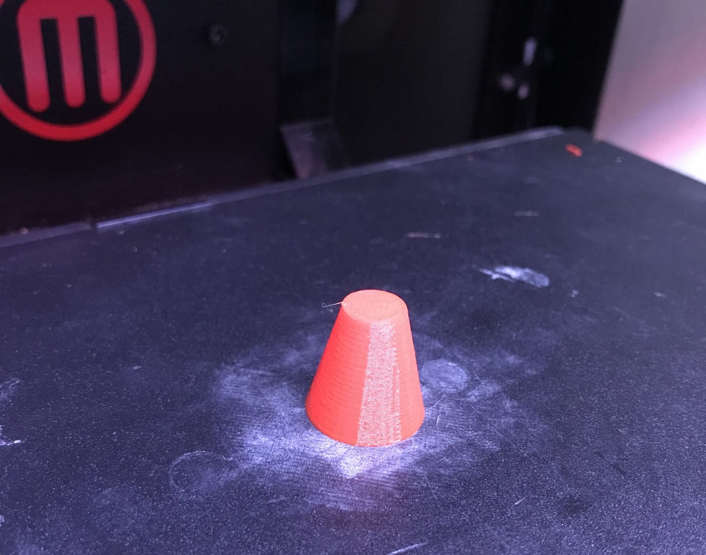
Run it, print it, and you should get the shape on the right.
That's it for this tutorial. Next time we'll go further down the stack and generate individual print-head moves. But first, just a bit about how this ties into mesh toolpathing. What we've done above is exactly what SingleMaterialFFFPrintGenerator is doing. However instead of directly using the mesh slice polygons as toolpaths, the PrintGenerator uses various toolpathing strategies to fill in each polygon with nested perimeters, dense and sparse infill, support, and so on. These are all done by IFillPolygon implementations like ShellsFillPolygon. Each of these classes takes an input polygon and outputs a set of 2D polygon and polyline Toolpaths that are passed to the layer Scheduler, exactly like we did above.
You can also use these toolpathing classes yourself. So, if you wanted to do standard shells-and-infill for your procedurally-generated polygons, you could use a ShellsFillPolygon to create the perimeter toolpaths. This class also returns the "inner" polygons, which you could then pass to a SparseLinesFillPolygon to get the infill toolpaths. Easy!