Mesh Simplification with g3Sharp
/[Update July 6, 2018] If you would like to test this Reducer implementation without writing C# code, you can try it in my new tool Cotangent, in the Simplify tool [/EndUpdate]
Recently a user posted a github issue asking for a mesh simplification example. It just so happened that I had recently finished writing an implementation of Garland and Heckbert's Quadric Error Metric (QEM) Simplification algorithm. If you want to learn more about this technique, the original papers and several later articles are available on Michael Garland's Website, and are very readable. I will give the broad strokes below, but first here is an example of what we are talking about - automatic reduction of a bunny mesh from 13,000 to 500 triangles:
An easy way to Simplify or Reduce a mesh (which is the terminology I use, because...well I don't have a good reason, but it's how I think of it!) is to iteratively collapse edges in the mesh. Each collapse removes one edges and the two (or one at the boundary) triangles connected to that edge, as well as one vertex. Just repeat until you hit your target triangle count, and you're done. Easy!
Except, which edge should you collapse first? And, when you collapse the edge, should you just keep the existing vertex position? In most cases it would at least make more sense to move the remaining vertex to the edge midpoint. But could we do better? This is where QEM comes in. Basically, the Quadric Error gives us a way to (1) "score" edges, so we know which edge collapses will have the smallest impact on the shape, and (2) predict a position for the new vertex that will minimize the score after the collapse.
Ultimately, the Quadric Error is a measurement of the sum-of-distances from a point to a set of planes. If you think of the ring of triangles around a vertex, each triangle makes a plane. The distance from the vertex to that plane is zero. But if we start moving the vertex, this distance increases. So we can "score" an a vertex movement (like an edge collapse) by measuring all the distances from the new vertex to all the input planes (of the original triangles). Each point-plane distance measurement can be expressed as a matrix multiply with the point, and since Ap+Bp = (A+B)p, we can combine all the error measurements into a single matrix multiplication!
Even better, after an edge collapse, we can think of that vertex as having a total error measured relative to the input planes of both vertices (still just one matrix). So as we do sequential collapses, we accumulate all the plane-distance-functions of the original mesh triangles that were (at some point in the past) connected to the remaining vertex. And it's still just one matrix. In the '99 paper linked from the site above [PDF], Garland showed how the QEM error is in some sense a measure of surface curvature, and produces "optimal" triangulations, under a reasonable definition of optimal. Amazing!
But, ok, you're probably just here for the code, right? To use the g3sharp implementation you need to get your mesh to be a DMesh3, see my previous tutorial for how to do that. Then you just need a couple lines to create a Reducer object and run the simplification:
DMesh3 mesh = load_my_mesh_somehow();
Reducer r = new Reducer(mesh);
r.ReduceToTriangleCount(500);
In the code above, 500 is the target triangle count. This takes a fraction of a second to run. I have not done extensive profiling, but on a relatively fast machine I can reduce a 350k mesh to 100k in 2 to 3 seconds. So, it's pretty fast.
Mesh Validity Checking
Most of the mesh processing algorithms in g3Sharp require that the input meshes be manifold. This term has lots of meanings, in this context it means that at minimum each mesh edge is connected 1 or 2 triangles. Inside DMesh3, edge triangles are stored in an Index2i object, so DMesh3 can't even represent a non-manifold edge. In most cases we also require that there are no bowtie vertices, which are vertices connected to disjoint sets of triangles. The simplest example of this would be two triangles connected only at one vertex (hence the name "bowtie").
If these conditions are not met, then some mesh operations - like an edge collapse - can produce undefined results, result in exceptions, and so on. So, to test that your mesh is internally consistent, you can use the DMesh3.CheckValidity() function. You can configure this function to have different behavior if the mesh is not valid, ie it can assert, throw an exception, just return false, and so on. By default it will consider bowtie vertices to be invalid, but you can also configure this behavior with the bAllowNonManifoldVertices argument.
Note that this function also does very thorough testing of the internal mesh data structures to make sure everything is consistent. So, it is relatively expensive, and you probably do not want to be calling it all the time in production code. One exception is when loading meshes from a file, in that case you really should check the meshes after reading, it can save you a lot of headaches trying to track down garbage-in/garbage-out type problems!
Preserving Boundaries
In some cases, for meshes with boundaries you might need to preserve the boundary loops exactly. For example if you are actually reducing a sub-region of a larger mesh, or a mesh split along UV boundaries. This just takes a few more lines, before your call to ReduceToTriangleCount():
r.SetExternalConstraints(new MeshConstraints());
MeshConstraintUtil.FixAllBoundaryEdges(r.Constraints, mesh);
The MeshConstraints object in the code above is in fact a very powerful facility, that allows you to constrain much more than just boundary edges. But that is a topic for a future tutorial. You can poke around the data structure, or the MeshConstraintUtil helper class, to find out more. The images below compare reducing a bunny-with-boundary to 500 triangles without (left) and with (right) a preserved boundary.
Here is a closeup of the boundary around the bunny's front paws. You see on the left that there are significantly shorter edges along the boundary loop, because it has been exactly preserved. However, you might also note if you look closely (or click to enlarge) that on the front-left paw that there are some thin sliver triangles. This is a current limitation of boundary preservation - it may result in a bit of ugly stuff at the border. This will hopefully be improved in future updates.

Project to Target
Finally, one last thing that you might want to do when Simplifying a mesh. By default, the "new" vertex position after an edge collapse is computed by minimizing the QEM error for that vertex. Compared to something like edge midpoints, this produces nicer shapes and actually results in the algorithm running much faster. However in some cases you may require that the vertex positions lie on the original mesh surface. This is also supported. First you build a spatial data structure, like the DMeshAABBTree3 we built in the Spatial Query tutorial, and then set that as a "Projection Target" for the Reducer. This causes the vertex positions to be mapped to the nearest points on the input mesh surface. Here is the code:
DMeshAABBTree3 tree = new DMeshAABBTree3(new DMesh3(mesh));
tree.Build();
MeshProjectionTarget target = new MeshProjectionTarget(tree.Mesh, tree);
r.SetProjectionTarget(target);
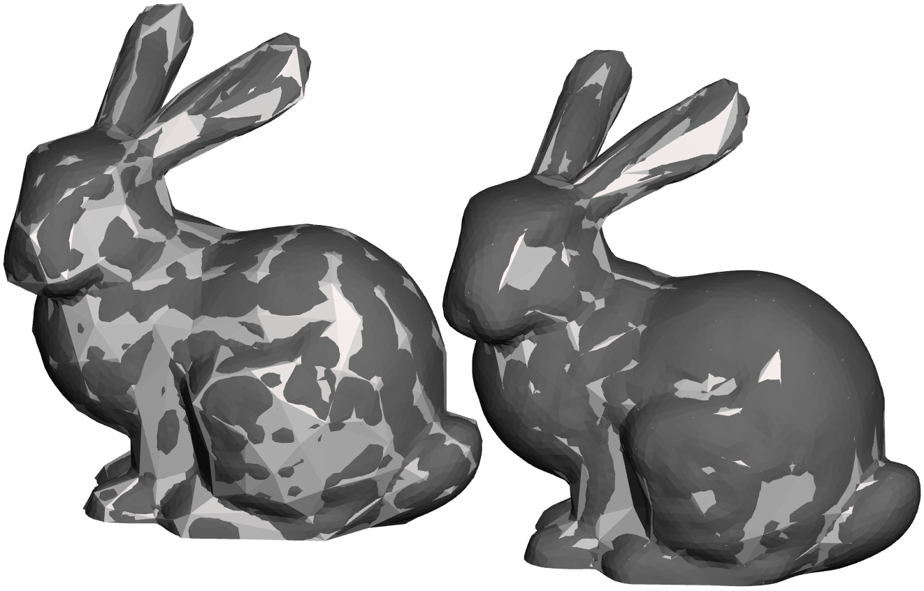
r.ProjectionMode = Reducer.TargetProjectionMode.Inline;The last line is optional. This causes the Reducer to compute the projection each time it wants to evaluate the QEM error for that vertex. This is "more correct" but many of these vertices will eventually be discarded, so the work is in some sense wasted (projections are expensive). If you leave this line out, then the projection is computed after the reducer is finished, for just the vertices that were ultimately kept. The image below compares no projection (left) and with inline projection (right), overlaid on the original surface (dark grey). The simplified meshes don't actually look very different, but you can see that on the right, most of the mesh is "inside" the original surface, while on the left it is roughly half-and-half inside/outside.
One thing to keep in mind with Projection is that for thin parts, the projection can easily end up on the "wrong" side. So, for most simplification problems you probably don't need it. Which is great because it's quite a bit slower!
Now, go save some triangles! Next up is Remeshing, which works in much the same way, only it's also much more complicated...