The Interactive Tools Framework in UE4.26 (at Runtime!)
/In this article, I am going to cover a lot of ground. I apologize in advance for the length. However, the topic of this article is essentially “How to Build 3D Tools using Unreal Engine”, which is a big one. By the end of this article, I will have introduced the Interactive Tools Framework, a system in Unreal Engine 4.26 that makes it relatively straightforward to build many types of interactive 3D Tools. I’m going to focus on usage of this Framework “at Runtime”, ie in a built Game. However, this exact same Framework is what we use to build the 3D Modeling Tools suite in the Unreal Editor. And, many of those Tools, are directly usable at Runtime! Sculpting in your Game! It’s pretty cool.
There is a short video of the ToolsFramworkDemo app to the right, and are a few screenshots below - this is a built executable, not running in the UE Editor (although that works, too). The demo allows you to create a set of meshes, which can be selected by clicking (multiselect supported with shift-click/ctrl-click), and a 3D transform gizmo is shown for the active selection. A small set of UI buttons on the left are used to do various things. The Add Bunny button will import and append a bunny mesh, and Undo and Redo do what you might expect. The World button toggles the Gizmo between World and Local coordinate systems.
The rest of the buttons launch various Modeling Tools, which are the exact same tool implementations as are used in Modeling Mode in the UE 4.26 Editor. PolyExtrude is the Draw Polygon Tool, in which you draw a closed polygon on a 3D workplane (which can be repositioned by ctrl-clicking) and then interactively set the extrusion height. PolyRevolve allows you to draw an open or closed path on a 3D workplane - double-click or close the path to end - and then edit the resulting surface of revolution. Edit Polygons is the PolyEdit tool from the Editor, here you can select faces/edges/vertices and move them with a 3D gizmo (note that the various PolyEdit sub-operations, like Extrude and Inset, are not exposed in the UI, but would work if they were). Plane Cut cuts the mesh with a workplane and Boolean does a mesh boolean (requires two selected objects). Remesh retriangulates the mesh (unfortunately I couldn’t easily display the mesh wireframe). Vertex Sculpt allows you to do basic 3D sculpting of vertex positions, and DynaSculpt does adaptive-topology sculpting, this is what I’ve shown being applied to the Bunny in the screenshot. Finally the Accept and Cancel buttons either Apply or Discard the current Tool result (which is just a preview) - I’ll explain this further below.
19/06/22 - This article is now somewhat out-of-date, and the sample project is broken in UE5. I have published a working port of the sample project to UE5 here: https://github.com/gradientspace/UE5RuntimeToolsFrameworkDemo, and an article about what has changed here: https://www.gradientspace.com/tutorials/2022/6/1/the-interactive-tools-framework-in-ue5 . If you are just interested in what changed in the code, the port was done in a single commit so you can browse the diffs.
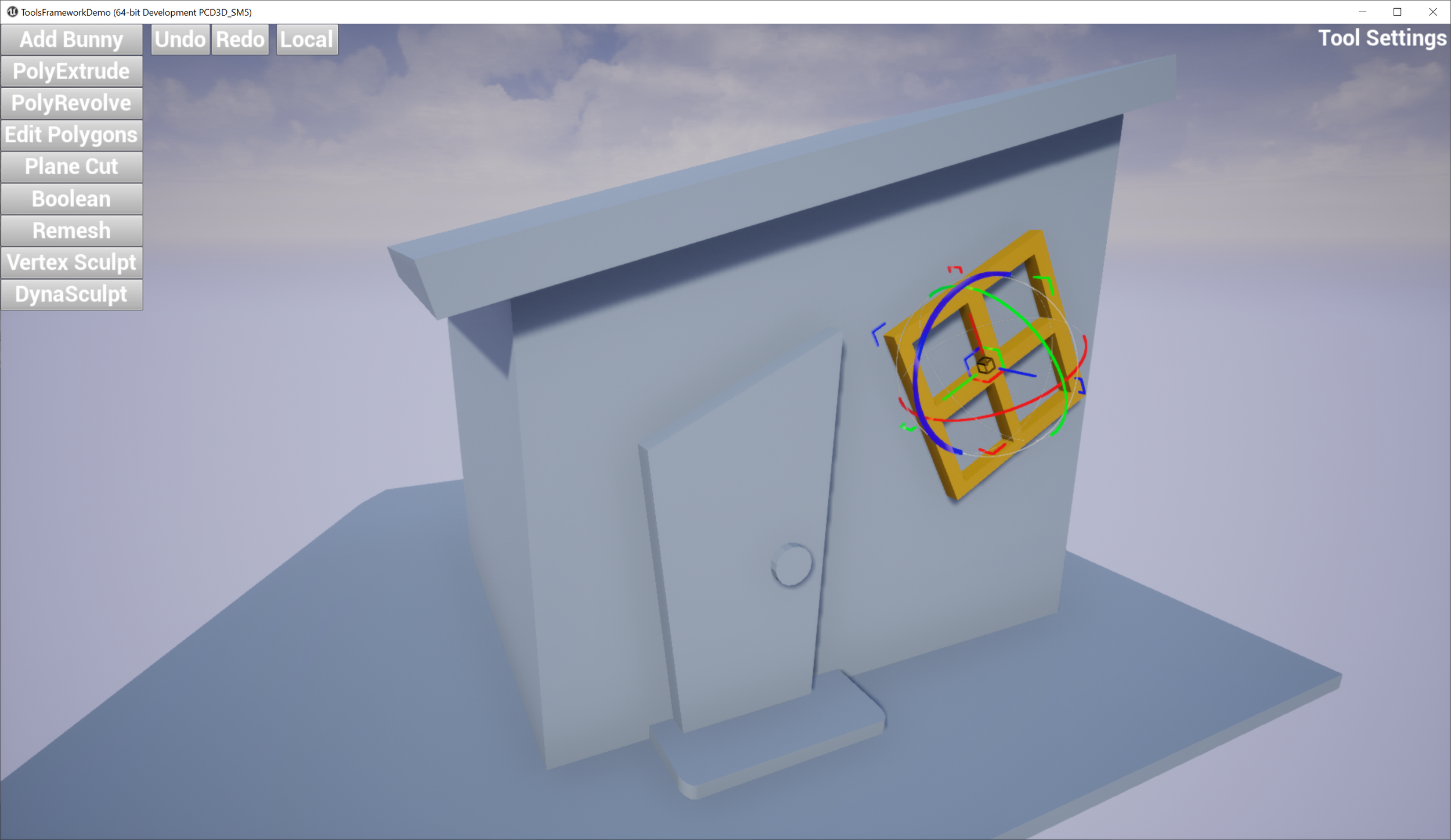
All This geometry was created in the demo. Window is selected and being rotated with gizmo.
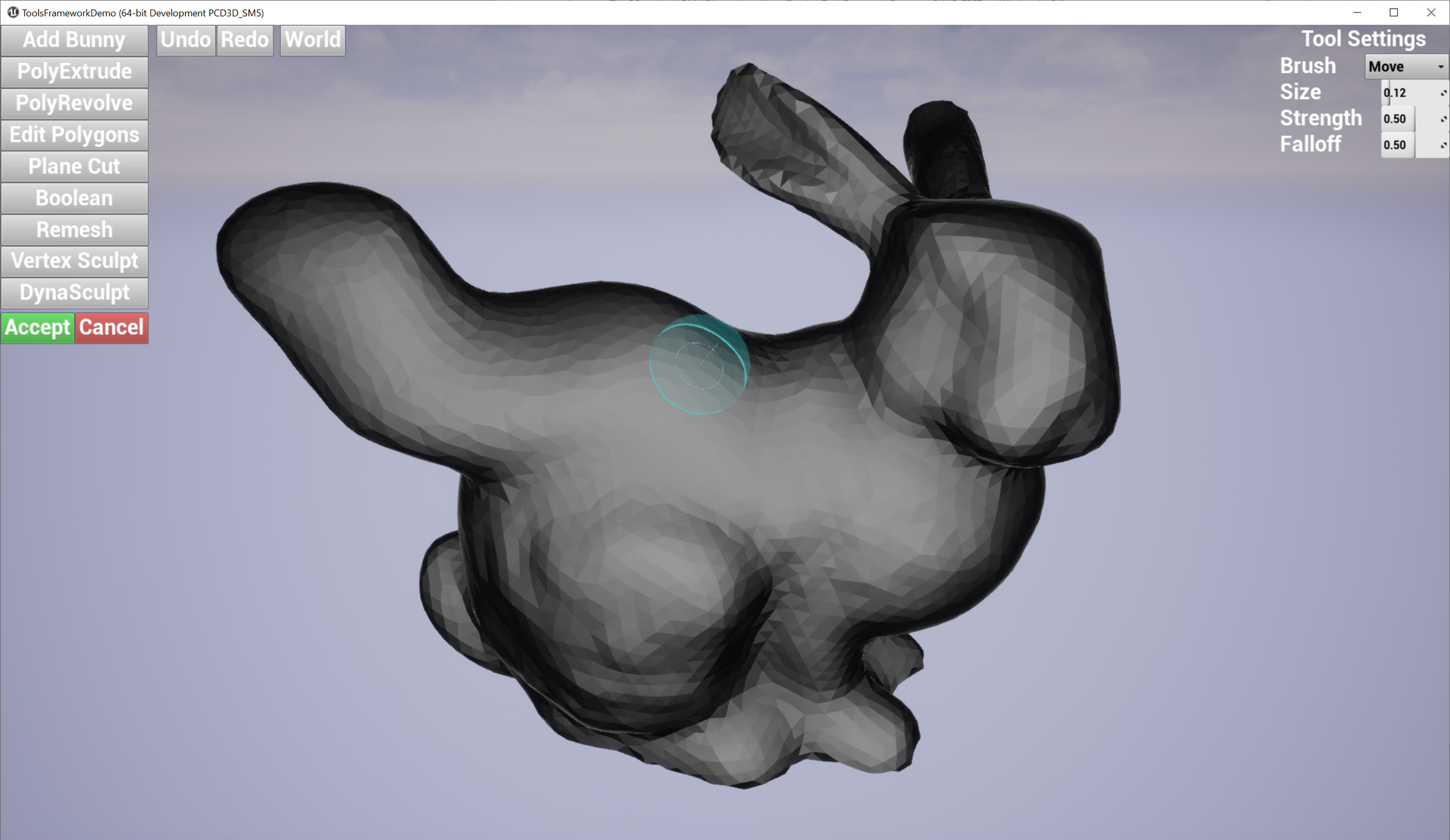
oh no bunny is growing some new parts
This is not a fully functional 3D Modeling tool, it’s just a basic demo. For one, there is no saving or export of any kind (wouldn’t be hard to add a quick OBJ export, though!). Support for assigning Materials is non-existent, the Materials you see are hardcoded or automatically used by the Tools (eg flat shading in the Dynamic Mesh Sculpting). Again, a motivated C++ developer could add things like that relatively easily. The 2D user interface is an extremely basic UMG user interface. I’m assuming that’s throw-away, and you would build your own UI. Then again, if you wanted to do a very simple domain-specific modeling tool, like say a 3D sculpting tool for cleaning up medical scans, you might be able to get away with this UI after a bit of spit-and-polish.
(Mandatory Disclaimer: your author, Ryan Schmidt, is an employee of Epic Games. However, gradientspace.com is his personal website and this article represents his personal thoughts and opinions. About triangles.)
Getting and Running The Sample Project
Before we begin, this tutorial is for UE 4.26, which you can install from the Epic Games Launcher. The project for this tutorial is on Github in the gradientspace UnrealRuntimeToolsFrameworkDemo repository (MIT License). Currently this project will only work on Windows as it depends on the MeshModelingToolset engine plugin, which is currently Windows-only. Getting that plugin to work on OSX/Linux would mainly be a matter of selective deleting, but it would require an Engine source build, and that’s beyond the scope of this tutorial.
Once you are in the top-level folder, right-click on ToolsFrameworkDemo.uproject in Windows Explorer and select Generate Visual Studio project files from the context menu. This will generate ToolsFrameworkDemo.sln, which you can use to open Visual Studio. You can also open the .uproject directly in the Editor (it will ask to compile), but you may want to refer to the C++ code to really understand what is going on in this project.
Build the solution and start (press F5) and the Editor should open into the sample map. You can test the project in PIE using the large Play button in the main toolbar, or click the Launch button to build a cooked executable. This will take a few minutes, after which the built game will pop up in a separate window. You can hit escape to exit full-screen, if it starts up that way (I think it’s the default). In full-screen, you’ll have to press Alt+F4 to exit as there is no menu/UI.
Overview
This article is so long it needs a table of contents. Here is what I am going to cover:
First, I am going to explain some background on the Interactive Tools Framework (ITF) as a concept. Where it came from, and what problem it is trying to solve. Feel free to skip this author-on-his-soapbox section, as the rest of the article does not depend on it in any way.
Next I will explain the major pieces of the UE4 Interactive Tools Framework. We will begin with Tools, ToolBuilders, and the ToolManager, and talk about Tool Life Cycles, the Accept/Cancel Model, and Base Tools. Input handling will be covered in The Input Behavior System, Tool settings stored via Tool Property Sets, and Tool Actions.
Next I will explain the Gizmos system, for implementing in-viewport 3D widgets, focusing on the Standard UTransformGizmo which is shown in the clips/images above.
At the highest level of the ITF, we have the Tools Context and ToolContext APIs, I’ll go into some detail on the 4 different APIs that a client of the ITF needs to implement - IToolsContextQueriesAPI, IToolsContextTransactionsAPI, IToolsContextRenderAPI, and IToolsContextAssetAPI. Then we’ll cover a few details specific to mesh editing Tools, in particular Actor/Component Selections, FPrimitiveComponentTargets, and FComponentTargetFactory.
Everything up to this point will be about the ITF modules that ship with UE4.26. To use the ITF at Runtime, we will create our own Runtime Tools Framework Back-End, which includes a rudimentary 3D scene of selectable mesh “scene objects”, a pretty standard 3D-app transform gizmo system, and implementations of the ToolsContext APIs I mentioned above that are compatible with this runtime scene system. This section is basically explaining the extra bits we have to add to the ITF to use it at Runtime, so you’ll need to read the previous sections to really understand it.
Next I’ll cover some material specific to the demo, including ToolsFrameworkDemo Project Setup that was necessary to get the demo to work, RuntimeGeometryUtils Updates, in particular collision support for USimpleDynamicMeshComponent, and then some notes on Using Modeling Mode Tools at Runtime, because this generally requires a bit of glue code to make the existing mesh editing Tools be functional in a game context.
And that’s it! Let’s begin…
Interactive Tools Framework - The Why
I don’t love the idea of starting an article about something by justifying it’s existence. But, I think I need to. I have spent many years - basically my entire career - building 3D Creation/Editing Tools. My first system was ShapeShop (which hasn’t been updated since 2008 but still works - a testament to Windows backwards compatibility!). I also built Meshmixer, which became an Autodesk product downloaded millions of times, and is widely used to this day. I am continually amazed to discover, via twitter search, what people are doing with Meshmixer (a lot of digital dentistry!!). I’ve also built other fully-functional systems that never saw the light of day, like this 3D Perspective Sketching interface we called Hand Drawn Worlds I built at Autodesk Research. After that, I helped to build some medical 3D design tools like the Archform dental aligner planning app and the NiaFit lower-leg prosthetic socket design tool (in VR!). Oh and Cotangent, which sadly I abandoned before it had any hope of catching on.
Self-congratulation aside, what I have learned over the last 15-odd years of making these 3D tools is that it is incredibly easy to make a giant mess. I started working on what became Meshmixer because Shapeshop had reached a point where it was just impossible to add anything to it. However, there were parts of Shapeshop that formed a very early “Tool Framework”, which I extracted and used as the basis for various other projects, and even bits of Meshmixer (which also ultimately became very brittle!). The code is still on my website. When I left Autodesk, I returned to this problem, of How To Build Tools, and created the frame3Sharp library which made it (relatively) easy to build at-Runtime 3D tools in a C# Game Engine. This framework grew around the Archform, NiaFit, and Cotangent apps mentioned above, and powers them to this day. But, then I joined Epic, and started over in C++!
So, that’s the origin story of the UE4 Interactive Tools Framework. Using this Framework, a small team (6-or-fewer people, depending on the month) has built Modeling Mode in UE4, which has over 50 “Tools”. Some are quite simple, like a Tool to Duplicate a thing with options, and some are extremely complex, like an entire 3D Sculpting Tool. But the critical point is, the Tools code is relatively clean and largely independent - nearly all of the Tools are a single self-contained cpp/h pair. Not independent by cutting-and-pasting, but independent in that, as much as possible, we have moved “standard” Tool functionality that would otherwise have to be duplicated, into the Framework.
Lets Talk About Frameworks
One challenge I have in explaining the Interactive Tools Framework is that I don’t have a point of reference to compare it to. Most 3D Content Creation tools have some level of “Tool Framework” in their codebase, but unless you have tried to add a feature to Blender, you probably have never interacted with these things. So, I can’t try to explain by analogy. And those tools don’t really try very hard to provide their analogous proto-frameworks as capital-F Frameworks. So it’s hard to get a handle on. (PS: If you think you know of a similar Framework, please get in touch and tell me!)
Frameworks are very common, though, in other kinds of Application Development. For example, if you want to build a Web App, or Mobile App, you are almost certainly going to be using a well-defined Framework like Angular or React or whatever is popular this month (there are literally hundreds). These Frameworks tend to mix low-level aspects like ‘Widgets’ with higher-level concepts like Views. I’m focusing on the Views here, because the vast majority of these Frameworks are based around the notion of Views. Generally the premise is that you have Data, and you want to put that data in Views, with some amount of UI that allows the user to explore and manipulate that Data. There’s even a standard term for it, “Model-View-Controller” architecture. The XCode Interface Builder is the best example I know of this, where you literally are storyboarding the Views that the user will see, and defining the App Behavior via transitions between these Views. Every phone app I use on a regular basis works this way.
Stepping up a level in complexity, we have Applications like, say, Microsoft Word or Keynote, which are quite different from a View-based Application. In these apps the user spends the majority of their time in a single View, and is directly manipulating Content rather than abstractly interacting with Data. But the majority of the manipulation is in the form of Commands, like deleting text, or editing Properties. For example in Word when I’m not typing my letters, I’m usually either moving my mouse to a command button so I can click on it - a discrete action - or opening dialog boxes and changing properties. What I don’t do is spend a lot of time using continuous mouse input (drag-and-drop and selection are notable exceptions).
Now consider a Content Creation Application like Photoshop or Blender. Again, as a user you spend the majority of your time in a standardized View, and you are directly manipulating Content rather than Data. There are still vast numbers of Commands and Dialogs with Properties. But many users of these apps - particularly in Creative contexts - also spend a huge amount of time very carefully moving the mouse while they hold down one of the buttons. Further, while they are doing this, the Application is usually in a particular Mode where the mouse-movement (often combined with modifier hotkeys) is being captured and interpreted in a Mode-specific way. The Mode allows the Application to disambiguate between the vast number ways that that the mouse-movement-with-button-held-down action could be interpreted, essentially to direct the captured mouse input to the right place. This is fundamentally different than a Command, which is generally Modeless, as well as Stateless in terms of in the Input Device.
In addition to Modes, a hallmark of Content Creation Applications are what I will refer to as Gizmos, which are additional transient interactive visual elements that are not part of the Content, but provide a (semi-Modeless) way to manipulate the Content. For example, small boxes or chevrons at the corners of a rectangle that can be click-dragged to resize the rectangle would be a standard example of a Gizmo. These are often called Widgets, but I think it’s confusing to use this term because of the overlap with button-and-menu Widgets, so I’ll use Gizmos.
So, now I can start to hint at what the Interactive Tool Framework is for. At the most basic level, it provides a systematic way to implement Modal States that Capture and Respond to User Input, which I’m going to call Interactive Tools or Tools for brevity, as well as for implementing Gizmos (which I will posit are essentially spatially-localized context-sensitive Modes, but we can save that discussion for Twitter).
Why Do I Need a Framework For This?
This is a question I have been asked many times, mainly by people who have not tried to build a complex Tool-based Application. The short answer is, to reduce (but sadly not eliminate) the chance that you will create an unholy disaster. But I’ll do a long one, too.
An important thing to understand about Tool-based applications is that as soon as you give users the option to use the Tools in any order, they will, and this will make everything much more complicated. In a View-based Application, the user is generally “On Rails”, in that the Application allows for doing X after Y but not before. When I start up the Twitter app, I can’t just jump directly to everything - I have to go through sequences of Views. This allows the developers of the Application to make vast assumptions about Application State. In particular, although Views might manipulate the same underlying DataModel (nearly always some form of database), I never have to worry about disambiguating a tap in one View from a tap in another. In some sense the Views are the Modes, and in the context of a particular View, there are generally only Commands, and not Tools.
As a result, in a View-based Application it is very easy to talk about Workflows. People creating View-based Applications tend to draw lots of diagrams that look like this:

These diagrams might be the Views themselves, but more often they are the steps a User would take through the Application - a User Story if you will. They are not always strictly linear, there can be branches and loops (a Google Image Search for Workflow has lots of more complex examples). But there are always well-defined entry and exit points. The User starts with a Task, and finishes with that Task completed, by way of the Workflow. It is then very natural to design an Application that provides the Workflow where the User can complete the Task. We can talk about Progress through the Workflow in a meaningful way, and the associated Data and Application State also make a kind of Progress. As additional Tasks are added, the job of the development team is to come up with a design that allows these necessary Workflows to be efficiently accomplished.

The fundamental complication in Content Creation/Editing Applications is that this methodology doesn’t apply to them at all. Ultimately the difference, I think, is that there is no inherent notion of Progress in a Content Creation/Editing Tool. For example, as a Powerpoint user, I can (and do!) spend hours re-organizing my slides, tweaking the image size and alignment, slightly adjusting text. In my mind I might have some nebulous notion of Progress, but this is not encoded in the Application. My Task is outside the Application. And without a clear Task or measure of Progress, there is no Workflow!
I think a more useful mental model for Content Creation/Editing Applications is like the image on the right. The green central hub the default state in these Applications, where generally you are just viewing your Content. For example Panning and Zooming your Image in Photoshop, or navigating around your 3D Scene in Blender. This is where the user spends a significant percentage of their time. The Blue spokes are the Tools. I go to a Tool for a while, but I always return to the Hub.
So if I were to track my state over time, it would be a winding path in and out of the default Hub, through untold numbers of Tools. There is no well-defined Order, as a user I am generally free to use the Tools in any Order I see fit. In a microcosm, we might be able to find small well-defined Workflows to analyze and optimize, but at the Application level, the Workflows are effectively infinite.
It might seem relatively obvious that the architectural approaches you need to take here are going to be different then in the Views approach. By squinting at it just the right way, one could argue that each Tool is basically a View, and so what is really different here? The difference, in my experience, is what I think of as Tool Sprawl.
If you have well-defined Workflows, then it is easy to make judgements about what is and isn’t necessary. Features that are extraneous to the required Workflows don’t just waste design and engineering time, they ultimately make the Workflows more complex than necessary - and that makes the User Experience worse! Modern software development orthodoxy is laser-focused on this premise - build the minimally viable product, and iterate, iterate, iterate to remove friction for the user.
Tool-based Applications are fundamentally different in that every additional Tool increases the value of the Application. If I have no use for a particular Tool, then except for the small UI overhead from the additional toolbar button necessary to launch the Tool, it’s addition hardly affects me at all. Of course, learning a new Tool will take some effort. But, the pay-off for that effort is this new Tool can now be combined with all the others! This leads to a sort of Application-level Network Effect, where each new Tool is a force-multiplier for all the existing Tools. This is immediately apparent if one observes virtually all major Content Creation/Editing Tools, where there are untold numbers of toolbars and menus of toolbars and nested tabs of toolbars, hidden behind other toolbars. To an outsider this looks like madness, but to the users, it’s the whole point.
Many people who come from the Workflow-oriented software world look upon these Applications in horror. I have observed many new projects where the team starts out trying to build something “simple”, that focuses on “core workflows”, perhaps for “novice users”, and lots of nice linear Workflow diagrams get drawn. But the reality is that Novice Users are only Novices until they have mastered your Application, and then they will immediately ask for more features. And so you will add a Tool here and there. And several years later you will have a sprawling set of Tools, and if you don’t have a systematic way to organize it all, you will have a mess on your hands.
Containing The Damage
Where does the mess come from? From what I have seen, there are a few very common ways to get in trouble. The first is just under-estimating the complexity of the task at hand. Many Content Creation Apps start out as “Viewers”, where all the app logic for things like 3D camera controls are done directly within the mouse and UI button handlers. Then over time new Editing functionality is incorporated by just adding more if/else branches or switch cases. This approach can carry on for quite a long time, and many 3D apps I have worked on still have these vestigial code-limbs at their core. But you’re just digging a deeper code-hole and filling it with code-spaghetti. Eventually, some actual software architecture will be needed, and painful refactoring efforts will be required (followed by years of fixing regressions, as users discover that all their favorite features are broken or work slightly differently now).
Even with some amount of “Tool Architecture”, how to handle device input is tricky, and often ends up leading to messy architectural lock-in. Given that “Tools” are often driven by device input, a seemingly-obvious approach is to directly give Tools input event handlers, like OnMouseUp/OnMouseMove/OnMouseDown functions. This becomes a natural place to put the code that “does things”, for example on a mouse event you might directly apply a brush stamp in a painting tool. Seems harmless until users ask for support for other input devices, like touch, or pen, or VR controllers. Now what? Do you just forward calls to your mouse handlers? What about pressure, or 3D position? And then comes automation, when users start asking for the ability to script what your Tool does. I have been in situations myself where “inject fake mouse event to force OnMouseX to run” started to seem like a viable solution (It is not. Absolutely not. Really, don’t).
Putting important code in input event handlers also leads to things like rampant copy-paste of standard event-handling patterns, which can be tedious to unwind if changes need to be made. And, expensive mouse event handlers will actually make your app feel less responsive than it ought to, due to something called mouse event priority. So, you really want to handle this part of your Tool Architecture carefully, because seemingly-standard design patterns can encourage a whole range of problems.
At the same time, if the Tools Architecture is too tightly defined, it can become a barrier to expanding the toolset, as new requirements come in that don’t “fit” the assumptions underlying the initial design. If many tools have been built on top of that initial architecture, it becomes intractable to change, and then clever Engineers are forced to come up with workarounds, and now you have two (or more) Tool Architectures. One of the biggest challenges is precisely how to divide up responsibilities between the Tool implementations and the Framework.
I can’t claim that the Interactive Tools Framework (ITF) will solve these problems for you. Ultimately, any successful software will end up being trapped by early design decisions, on top of which mountains have been built, and changing course can only happen at great expense. I could tell you stories all day, about how I have done this to myself. What I can say is, the ITF as realized in UE4 hopefully benefits from my past mistakes. Our experience with people using the ITF to build new Tools in the UE4 Editor over the past 2 years has (so far) been relatively painless, and we are continually looking for ways to smooth out any points of friction that do come up.
Tools, ToolBuilders, and the ToolManager
As I laid out above, an Interactive Tool is a Modal State of an Application, during which Device Input can be captured and interpreted in a specific way. In the Interactive Tools Framework (ITF), the UInteractiveTool base class represents the Modal State, and has a very small set of API functions that you are likely to need to implement. Below I have summarized the core UInteractiveTool API in psuedo-C++ (I have omitted things like virtual, const, optional arguments, etc, for brevity). There are other sets of API functions that we will cover to some extent later, but these are the critical ones. You initialize your Tool in ::Setup(), and do any finalization and cleanup in ::Shutdown(), which is also where you would do things like an ‘Apply’ operation. EToolShutdownType is related to the HasAccept() and CanAccept() functions, I will explain more below. Finally a Tool will be given a chance to Render() and Tick each frame. Note that there is also a ::Tick() function, but you should override ::OnTick() as the base class ::Tick() has critical functionality that must always run.
UCLASS()
class UInteractiveTool : public UObject, public IInputBehaviorSource
{
    void Setup();
    void Shutdown(EToolShutdownType ShutdownType);
    void Render(IToolsContextRenderAPI* RenderAPI);
    void OnTick(float DeltaTime);

    bool HasAccept();
    bool CanAccept();
};
A UInteractiveTool is not a standalone object, you cannot simply spawn one yourself. For it to function, something must call Setup/Render/Tick/Shutdown, and pass appropriate implementations of things like the IToolsContextRenderAPI, which allow the Tool to draw lines/etc. I will explain further below. But for now what you need to know is, to create a Tool instance, you will need to request one from a UInteractiveToolManager. To allow the ToolManager to build arbitrary types, you register a <String, UInteractiveToolBuilder> pair with the ToolManager. The UInteractiveToolBuilder is a very simple factory-pattern base class that must be implemented for each Tool type:
UCLASS()
class UInteractiveToolBuilder : public UObject
{
    bool CanBuildTool(const FToolBuilderState& SceneState);
    UInteractiveTool* BuildTool(const FToolBuilderState& SceneState);
};
The main API for UInteractiveToolManager is summarized below. Generally you will not need to implement your own ToolManager, the base implementation is fully functional and should do everything required to use Tools. But you are free to extend the various functions in a subclass, if necessary.
The functions below are listed in roughly the order you would call them. RegisterToolType() associates the string identifier with a ToolBuilder implementation. The Application then sets an active Builder using SelectActiveToolType(), and then ActivateTool() to create a new UInteractiveTool instance. There are getters to access the active Tool, but there is rarely call to do this frequently, in practice. The Render() and Tick() functions must be called each frame by the Application, which then call the associated functions for the active Tool. Finally DeactiveTool() is used to terminate the active Tool.
UCLASS()
class UInteractiveToolManager : public UObject, public IToolContextTransactionProvider
{
    void RegisterToolType(const FString& Identifier, UInteractiveToolBuilder* Builder);
    bool SelectActiveToolType(const FString& Identifier);
    bool ActivateTool();

    void Tick(float DeltaTime);
    void Render(IToolsContextRenderAPI* RenderAPI);

    void DeactivateTool(EToolShutdownType ShutdownType);
};
Tool Life Cycle
At the high level, the Life Cycle of a Tool is as follows
ToolBuilder is registered with ToolManager
Some time later, User indicates they wish to start Tool (eg via button)
UI code sets Active ToolBuilder, Requests Tool Activation
ToolManager checks that ToolBuilder.CanBuildTool() = true, if so, calls BuildTool() to create new instance
ToolManager calls Tool Setup()
Until Tool is deactivated, it is Tick()’d and Render()’d each frame
User indicates they wish to exit Tool (eg via button, hotkey, etc)
ToolManager calls Tool Shutdown() with appropriate shutdown type
Some time later, Tool instance is garbage collected
Note the last step. Tools are UObjects, so you cannot rely on the C++ destructor for cleanup. You should do any cleanup, such as destroying temporary actors, in your Shutdown() implementation.
EToolShutdownType and the Accept/Cancel Model
A Tool can support termination in two different ways, depending on what type of interactions the Tool supports. The more complex alternative is a Tool which can be Accepted (EToolShutdownType::Accept) or Cancelled (EToolShutdownType::Cancel). This is generally used when the Tool’s interaction supports some kind of live preview of an operation, that the user may wish to discard. For example, a Tool that applies a mesh simplification algorithm to a selected Mesh likely has some parameters the user may wish to explore, but if the exploration is unsatisfactory, the user may prefer to not apply the simplification at all. In this case, the UI can provide buttons to Accept or Cancel the active Tool, which result in calls to ToolManager::DeactiveTool() with the appropriate EToolShutdownType value.
The second termination alternative - EToolShutdownType::Completed - is simpler in that it simply indicates that the Tool should “exit”. This type of termination can be used to handle cases where there is no clear ‘Accept’ or ‘Cancel’ action, for example in Tools that simply visualize data, Tools where editing operations are applied incrementally (eg spawning objects based on click points), and so on.
To be clear, you do not need to use or support Accept/Cancel-style Tools in your usage of the ITF. Doing so generally results in a more complex UI. And if you support Undo in your application, then even Tools that could have Accept and Cancel options, can equivalently be done as Complete-style Tools, and the user can Undo if they are unhappy. However, if the Tool completion can involve lengthy computations or is destructive in some way, supporting Accept/Cancel tends to result in a better user experience. In the UE Editor’s Modeling Mode, we generally use Accept/Cancel when editing Static Mesh Assets for precisely this reason.
Another decision you will have to make is how to handle the modal nature of Tools. Generally it is useful to think of the user as being “in” a Tool, ie in the particular Modal state. So how do they get “out”? You can require the user to explicitly click Accept/Cancel/Complete buttons to exit the active Tool, this is the simplest and most explicit, but does mean clicks are necessary, and the user has to mentally be aware of and manage this state. Alternately you could automatically Accept/Cancel/Complete when the user selects another Tool in the Tool toolbar/menu/etc (for example). However this raises a thorny issue of whether one should auto-Accept or auto-Cancel. There is no right answer to this question, you must decide what is best for your particular context (although in my experience, auto-Cancelling is can be quite frustrating when one accidentally mis-clicks!)
Base Tools
One of the main goals of the ITF is to reduce the amount of boilerpate code necessary to write Tools, and improve consistency. Several “tool patterns” come up so frequently that we have included standard implementations of them in the ITF, in the /BaseTools/ subfolder. Base Tools generally include one or more InputBehaviors (see below), whose actions are mapped to virtual functions you can override and implement. I will briefly describe each of these Base Tools as they are both a useful way to build your own Tools, and a good source of sample code for how to do things:
USingleClickTool captures mouse-click input and, if the IsHitByClick() function returns a valid hit, calls OnClicked() function. You provide implementations of both of these. Note that the FInputDeviceRay structure here includes both a 2D mouse position, and 3D ray.
class INTERACTIVETOOLSFRAMEWORK_API USingleClickTool : public UInteractiveTool
{
    FInputRayHit IsHitByClick(const FInputDeviceRay& ClickPos);
    void OnClicked(const FInputDeviceRay& ClickPos);
};
UClickDragTool captures and forwards continuous mouse, input instead of a single click. If CanBeginClickDragSequence() returns true (generally you would do a hit-test here, similar to USingleClickTool), then OnClickPress() / OnClickDrag() / OnClickRelease() will be called, similar to standard OnMouseDown/Move/Up event patterns. Note, however, that you must handle the case where the sequence aborts without a Release, in OnTerminateDragSequence().
class INTERACTIVETOOLSFRAMEWORK_API UClickDragTool : public UInteractiveTool
{
    FInputRayHit CanBeginClickDragSequence(const FInputDeviceRay& PressPos);
    void OnClickPress(const FInputDeviceRay& PressPos);
    void OnClickDrag(const FInputDeviceRay& DragPos);
    void OnClickRelease(const FInputDeviceRay& ReleasePos);
    void OnTerminateDragSequence();
};
UMeshSurfacePointTool is similar to UClickDragTool in that it provides a click-drag-release input handling pattern. However, UMeshSurfacePointTool assumes that it is acting on a target UPrimitiveComponent (how it gets this Component will be explained below). The default implementation of the HitTest() function below will use standard LineTraces (so you don’t have to override this function if that is sufficient). UMeshSurfacePointTool also supports Hover, and tracks the state of Shift and Ctrl modifier keys. This is a good starting point for simple “draw-on-surface” type tools, and many of the Modeling Mode Tools derive from UMeshSurfacePointTool. (One small note: this class also supports reading stylus pressure, however in UE4.26 stylus input is Editor-Only) ((Extra Note: Although it is named UMeshSurfacePointTool, it does not actually require a Mesh, just a UPrimitiveComponent that supports a LineTrace))
class INTERACTIVETOOLSFRAMEWORK_API UMeshSurfacePointTool : public UInteractiveTool
{
    bool HitTest(const FRay& Ray, FHitResult& OutHit);
    void OnBeginDrag(const FRay& Ray);
    void OnUpdateDrag(const FRay& Ray);
    void OnEndDrag(const FRay& Ray);

    void OnBeginHover(const FInputDeviceRay& DevicePos);
    bool OnUpdateHover(const FInputDeviceRay& DevicePos);
    void OnEndHover();
};
There is a fourth Base Tool, UBaseBrushTool, that extends UMeshSurfacePointTool with various functionality specific to Brush-based 3D Tool, ie a surface painting brush, 3D sculpting tool, and so on. This includes a set of standard brush properties, a 3D brush position/size/falloff indicator, tracking of “brush stamps”, and various other useful bits. If you are building brush-style Tools, you may find this useful.
FToolBuilderState
The UInteractiveToolBuilder API functions both take a FToolBuilderState argument. The main purpose of this struct is to provide Selection information - it indicates what the Tool would or should act on. Key fields of the struct are shown below. The ToolManager will construct a FToolBuilderState and pass it to the ToolBuilders, which will then use it to determine if they can operate on the Selection. Both Actors and Components can be passed, but also only Actors and Components, in the UE4.26 ITF implementation. Note that if a Component appears in SelectedComponents, then it’s Actor will be in SelectedActors. The UWorld containing these Actors is also included.
struct FToolBuilderState
{
    UWorld* World;
    TArray<AActor*> SelectedActors;
    TArray<UActorComponent*> SelectedComponents;
};
In the Modeling Mode Tools, we do not directly operate on Components, we wrap them in an standard container, so that we can, for example, 3D sculpt “any” mesh Component that has a container implementation. This is largely why I can write this tutorial, because I can make those Tools edit other types of meshes, like Runtime meshes. But when building your own Tools, you are free to ignore FToolBuilderState. Your ToolBuilders can use any other way to query scene state, and your Tools are not limited to acting on Actors or Components.
On ToolBuilders
A frequent question that comes up among users of the ITF is whether the UInteractiveToolBuilder is necessary. In the simplest cases, which are the most common, your ToolBuilder will be straightforward boilerplate code (unfortunately since it is a UObject, this boilerplate cannot be directly converted to a C++ template). The utility of ToolBuilders arises when one starts to re-purpose existing UInteractiveTool implementations to solve different problems.
For example, in the UE Editor we have a Tool for editing mesh polygroups (effectively polygons), called PolyEdit. We also have a very similar tool for editing mesh triangles, called TriEdit. Under the hood, these are the same UInteractiveTool class. In TriEdit mode, the Setup() function configures various aspects of the Tool to be appropriate for triangles. To expose these two modes in the UI, we use two separate ToolBuilders, which set a “bIsTriangleMode” flag on the created Tool instance after it is allocated, but before Setup() runs.
I certainly won’t claim this is an elegant solution. But, it was expedient. In my experience, this situation arises all the time as your set of Tools evolves to handle new situations. Frequently an existing Tool can be shimmed in to solve a new problem with a bit of custom initialization, a few additional options/properties, and so on. In an ideal world one would refactor the Tool to make this possible via subclassing or composition, but we rarely live in the ideal world. So, the bit of unsightly code necessary to hack a Tool to do a second job, can be placed in a custom ToolBuilder, where it is (relatively) encapsulated.
The string-based system for registering ToolBuilders with the ToolManager can allow your UI level (ie button handlers and so on) to launch Tools without having to actually know about the Tool class types. This can often allow for a cleaner separation of concerns when building the UI. For example, in the ToolsFrameworkDemo I will describe below, the Tools are launched by UMG Blueprint Widgets that simply pass string constants to a BP Function - they have no knowledge of the Tool system at all. However, the need to set an ‘Active’ builder before spawning a Tool is somewhat of a vestigial limb, and these operations will likely be combined in the future.
The Input Behavior System
Above I stated that “An Interactive Tool is a Modal State of an Application, during which Device Input can be captured and interpreted in a specific way”. But the UInteractiveTool API does not have any mouse input handler functions. This is because Input Handling is (mostly) decoupled from the Tools. Input is captured and interpreted by UInputBehavior objects that the Tool creates and registers with the UInputRouter, which “owns” the input devices and routes input events to the appropriate Behavior.
The reason for this separation is that the vast majority of input handling code is cut-and-pasted, with slight variations in how particular interactions are implemented. For example consider a simple button-click interaction. In a common event API you would have something like OnMouseDown(), OnMouseMove(), and OnMouseUp() functions that can be implemented, and lets say you want to map from those events to a single OnClickEvent() handler, for a button press-release action. A surprising number of applications (particularly web apps) will fire the click in OnMouseDown - which is wrong! But, blindly firing OnClickEvent in OnMouseUp is also wrong! The correct behavior here is actually quite complex. In OnMouseDown(), you must hit-test the button, and begin capturing mouse input. In OnMouseUp, you have to hit-test the button again, and if the cursor is still hitting the button, only then is OnClickEvent fired. This allows for cancelling a click and is how all serious UI toolkits have it implemented (try it!).
If you have even tens of Tools, implementing all this handling code, particularly for multiple devices, becomes very error-prone. So for this reason, the ITF moves these little input-event-handling state machines into UInputBehavior implementations which can be shared across many tools. In fact a few simple behaviors like USingleClickInputBehavior, UClickDragBehavior, and UHoverBehavior handle the majority of cases for mouse-driven interaction. The Behaviors then forward their distilled events to target objects via simple interfaces that something like a Tool or Gizmo can implement. For example USingleClickInputBehavior can act on anything that implemments IClickBehaviorTarget, which just has two functions - IsHitByClick() and OnClicked(). Note that because the InputBehavior doesn’t know what it is acting on - the “button” could be a 2D rectangle or an arbitrary 3D shape - the Target interface has to provide the hit-testing functionality.
Another aspect of the InputBehavior system is that Tools do not directly talk to the UInputRouter. They only provide a list of UInputBehavior’s that they wish to have active. The additions to the UInteractiveTool API to support this are shown below. Generally, in a Tool’s ::Setup() implementation, one or more Input Behaviors are created and configured, and passed to AddInputBehavior. The ITF then calls GetInputBehaviors when necessary, to register those behaviors with the UInputRouter. Note: currently the InputBehavior set cannot change dynamically during the Tool, however you can configure your Behaviors to ignore events based on whatever criteria you wish.
class UInteractiveTool : public UObject, public IInputBehaviorSource
{
    // ...previous functions...

    void AddInputBehavior(UInputBehavior* Behavior);
    const UInputBehaviorSet* GetInputBehaviors();
};
The UInputRouter is similar to the UInteractiveToolManager in that the default implementation is sufficient for most usage. The only job of the InputRouter is to keep track of all the active InputBehaviors and mediate capture of the input device. Capture is central to input handling in Tools. When a MouseDown event comes into the InputRouter, it checks with all the registered Behaviors to ask if they want to start capturing the mouse event stream. For example if you press down over a button, that button’s registered USingleClickInputBehavior would indicate that yes, it wants to start capturing. Only a single Behavior is allowed to capture input at a time, and multiple Behaviors (which don’t know about eachother) might want to capture - for example, 3D objects that are overlapping from the current view. So, each Behavior returns a FInputCaptureRequest that indicates “yes” or “no” along with depth-test and priority information. The UInputRouter then looks at all the capture requests and, based on depth-sorting and priority, selects one Behavior and tells it that capture will begin. Then MouseMove and MouseRelease events are only passed to that Behavior until the Capture terminates (usually on MouseRelease).
In practice, you will rarely have to interact with UInputRouter when using the ITF. Once the connection between application-level mouse events and the InputRouter is established, you shouldn’t ever need to touch it again. This system largely deals away with common errors like mouse handling “getting stuck” due to a capture gone wrong, because the UInputRouter is ultimately in control of mouse capture, not individual Behaviors or Tools. In the accompanying ToolsFrameworkDemo project, I have implemented everything necessary for the UInputRouter to function.
The basic UInputBehavior API is shown below. The FInputDeviceState is a large structure that contains all input device state for a given event/time, including status of common modifier keys, mouse button state, mouse position, and so on. One main difference from many input events is that the 3D World-Space Ray associated with the input device position is also included.
UCLASS()
class UInputBehavior : public UObject
{
    FInputCapturePriority GetPriority();
    EInputDevices GetSupportedDevices();

    FInputCaptureRequest WantsCapture(const FInputDeviceState& InputState);
    FInputCaptureUpdate BeginCapture(const FInputDeviceState& InputState);
    FInputCaptureUpdate UpdateCapture(const FInputDeviceState& InputState);
    void ForceEndCapture(const FInputCaptureData& CaptureData);

    // ... hover support...
}
I have omitted some extra parameters in the above API, to simplify things. In particular if you implement your own Behaviors, you will discover there is an EInputCaptureSide enum passed around nearly everywhere, largely as a default EInputCaptureSide::Any. This is for future use, to support the situation where a Behavior might be specific to a VR controller in either hand.
However, for most apps you will likely find that you never actually have to implement your own Behavior. A set of standard behaviors, such as those mentioned above, is included in the /BaseBehaviors/ folder of the InteractiveToolFramework module. Most of the standard Behaviors are derived from a base class UAnyButtonInputBehavior, which allows them to work with any mouse button, including “custom” buttons defined by a TFunction (which could be a keyboard key)! Similarly the standard BehaviorTarget implementations all derive from IModifierToggleBehaviorTarget, which allows for arbitrary modifier keys to be configured on a Behavior and forwarded to the Target without having to subclass or modify the Behavior code.
Direct Usage of UInputBehaviors
In the discussion above, I focused on the case where a UInteractiveTool provides a UInputBehaviorSet. Gizmos will work similarly. However, the UInputRouter itself is not aware of Tools at all, and it is entirely possible to use the InputBehavior system separately from either. In the ToolsFrameworkDemo, I implemented the click-to-select-meshes interaction this way, in the USceneObjectSelectionInteraction class. This class implements IInputBehaviorSource and IClickBehaviorTarget itself, and is just owned by the framework back-end subsystem. Even this is not strictly necessary - you can directly register a UInputBehavior you create yourself with the UInputRouter (note, however, that due to an API oversight on my part, in UE4.26 you cannot explicitly unregister a single Behavior, you can only unregister by source).
Non-Mouse Input Devices
Additional device types are currently not handled in the UE4.26 ITF implementation, however the previous iteration of this behavior system in frame3Sharp supported touch and VR controller input, and these should (eventually) work similarly in the ITF design. The general idea is that only the InputRouter and Behaviors need to explicitly know about different input modalities. An IClickBehaviorTarget implementation should work similarly with a mouse button, finger tap, or VR controller click, but also nothing rules out additional Behavior Targets tailored for device-specific interactions (eg from a two-finger pinch, spatial controller gesture, and so on). Tools can register different Behaviors for different device types, the InputRouter would take care of handling which devices are active and capturable.
Currently, some level of handling of other device types can be accomplished by mapping to mouse events. Since the InputRouter does not directly listen to the input event stream, but rather the ITF back-end creates and forwards events, this is a natural place to do such mappings, some more detail will be explained below.
A Limitation - Capture Interruption
One limitation of this system which is important to be aware of when designing your interactions is that “interruption” of an active capture is not yet supported by the framework. This most frequently arises when one wishes to have an interaction that would either be a click, or a drag, depending on if the mouse is immediately released in the same location, or moved some threshold distance. In simple cases this can be handled via UClickDragBehavior, with your IClickDragBehaviorTarget implementation making the determination. However, if the click and drag actions need to go to very different places that are not aware of eachother, this may be painful. A cleaner way to support this kind of interaction is to allow one UInputBehavior to “interrupt” another - in this case, the drag to “interrupt” the click’s active capture when it’s preconditions (ie sufficient mouse movement) are met. This is an area of the ITF that may be improved in the future.
Tool Property Sets
UInteractiveTool has one other set of API functions that I haven’t covered, which is for managing a set of attached UInteractiveToolPropertySet objects. This is a completely optional system that is somewhat tailored for usage in the UE Editor. For Runtime usage it is less effective. Essentially UInteractiveToolPropertySet’s are for storing your Tool Settings and Options. They are UObjects with UProperties, and in the Editor, these UObjects can be added to a Slate DetailsView to automatically expose those properties in the Editor UI.
The additional UInteractiveTool APIs are summarized below. Generally in the Tool ::Setup() function, various UInteractiveToolPropertySet subclasses will be created and passed to AddToolPropertySource(). The ITF back-end will use the GetToolProperties() function to initialize the DetailsView panel, and then the Tool can show and hide property sets dynamically using SetToolPropertySourceEnabled()
class UInteractiveTool : public UObject, public IInputBehaviorSource
{
    // ...previous functions...
public:
    TArray<UObject*> GetToolProperties();
protected:
    void AddToolPropertySource(UObject* PropertyObject);
    void AddToolPropertySource(UInteractiveToolPropertySet* PropertySet);
    bool SetToolPropertySourceEnabled(UInteractiveToolPropertySet* PropertySet, bool bEnabled);
};
In the UE Editor, UProperties can be marked up with meta tags to control the generated UI widgets - things like slider ranges, valid integer values, and enabling/disabling widgets based on the value of other properties. Much of the UI in the Modeling Mode works this way.
Unfortunately, UProperty meta tags are not available at Runtime, and the DetailsView panels are not supported in UMG Widgets. As a result, the ToolPropertySet system becomes much less compelling. It does still provide some useful functionality though. For one, the Property Sets support saving and restoring their Settings across Tool invocations, using the SaveProperties() and RestoreProperties() functions of the property set. You simply call SaveProperties() on each property set in your Tool Shutdown(), and RestoreProperties() in ::Setup().
A second useful ability is the WatchProperty() function, which allows for responding to changes in PropertySet values without any kind of change notification. This is necessary with UObjects because C++ code can change a UProperty on a UObject directly, and this will not cause any kind of change notification to be sent. So, the only way to reliably detect such changes is via polling. Yes, polling. It’s not ideal, but do consider that (1) a Tool necessarily has a limited number of properties that a user can possibly handle and (2) only one Tool is active at a time. To save you from having to implement a stored-value-comparison for each property in your ::OnTick(), you can add watchers using this pattern:
MyPropertySet->WatchProperty( MyPropertySet->bBooleanProp, [this](bool bNewValue) { // handle change! } );In UE4.26 there are some additional caveats (read: bugs) that must be worked around, see below for more details.
Tool Actions
Finally, the last major part of the UInteractiveTool API is support for Tool Actions. These are not widely used in the Modeling Mode toolset, except to implement hotkey functionality. However, the Tool Actions are not specifically related to hotkeys. What they allow is for a Tool to expose “Actions” (ie parameterless functions) that can be called via integer identifiers. The Tool constructs and returns a FInteractiveToolActionSet, and then higher-level client code can enumerate these actions, and execute them using the ExecuteAction function defined below.
class UInteractiveTool : public UObject, public IInputBehaviorSource
{
    // ...previous functions...
public:
    FInteractiveToolActionSet* GetActionSet();
    void ExecuteAction(int32 ActionID);
protected:
    void RegisterActions(FInteractiveToolActionSet& ActionSet);
};
The sample code below shows two Tool Actions being registered. Note that although the FInteractiveToolAction contains a hotkey and modifier, these are only suggestions to the higher-level client. The UE Editor queries Tools for Actions, and then registers the suggested hotkeys as Editor hotkeys, which allows the user to remap them. UE does not have any kind of similar hotkey system at Runtime, you would need to manually map these hotkeys yourself
void UDynamicMeshSculptTool::RegisterActions(FInteractiveToolActionSet& ActionSet)
{
    ActionSet.RegisterAction(this, (int32)EStandardToolActions::BaseClientDefinedActionID + 61,
        TEXT("SculptDecreaseSpeed"),
        LOCTEXT("SculptDecreaseSpeed", "Decrease Speed"),
        LOCTEXT("SculptDecreaseSpeedTooltip", "Decrease Brush Speed"),
        EModifierKey::None, EKeys::W,
        [this]() { DecreaseBrushSpeedAction(); });

    ActionSet.RegisterAction(this, (int32)EStandardToolActions::ToggleWireframe,
        TEXT("ToggleWireframe"),
        LOCTEXT("ToggleWireframe", "Toggle Wireframe"),
        LOCTEXT("ToggleWireframeTooltip", "Toggle visibility of wireframe overlay"),
        EModifierKey::Alt, EKeys::W,
        [this]() { ViewProperties->bShowWireframe = !ViewProperties->bShowWireframe; });
}
Ultimately each ToolAction payload is stored as a TFunction<void()>. If you are just forwarding to another Tool function, like the DecreaseBrushSpeedAction() call above, you don’t necessarily benefit from the ToolAction system, and there is no need to use it at all. However due to current limitations with Tool exposure to Blueprints, ToolActions (because they can be called via a simple integer) may be an effective way to expose Tool functionality to BP without having to write many wrapper functions.
Gizmos
As I have mentioned, “Gizmo” refers to those little in-viewport clicky-things we use in 2D and 3D Content Creation/Editing Apps to let you efficiently manipulate parameters of visual elements or objects. If you’ve used any 3D tool, you have almost certainly used a standard Translate/Rotate/Scale Gizmo, for example. Like Tools, Gizmos capture user input, but instead of being a full Modal state, a Gizmo is generally transient, ie Gizmos can come and go, and you can have multiple Gizmos active at the same time, and they only capture input if you click “on” them (what “on” means can be a bit fuzzy). Because of this, Gizmos generally require some specific visual representation that allows the user to indicate when they want to “use” the Gizmo, but conceptually you can also have a Gizmo that does this based on a hotkey or application state (eg checkbox).
In the Interactive Tools Framework, Gizmos are implemented as subclasses of UInteractiveGizmo, which is very similar to UInteractiveTool:
UCLASS()
class UInteractiveGizmo : public UObject, public IInputBehaviorSource
{
    void Setup();
    void Shutdown();
    void Render(IToolsContextRenderAPI* RenderAPI);
    void Tick(float DeltaTime);

    void AddInputBehavior(UInputBehavior* Behavior);
    const UInputBehaviorSet* GetInputBehaviors();
}
And similarly Gizmo instances are managed by a UInteractiveGizmoManager, using UInteractiveGizmoBuilder factories registered via strings. Gizmos use the same UInputBehavior setup, and are similarly Rendered and be Ticked every frame by the ITF.
At this high level, the UInteractiveGizmo is just a skeleton, and to implement a custom Gizmo you will have to do quite a bit of work yourself. Unlike Tools, it’s more challenging to provide “base” Gizmos because of the visual-representation aspect. In particular, the standard InputBehaviors will require that you are able to do raycast hit-testing against your Gizmo, and so you can’t just draw arbitrary geometry in the Render() function. That said, the ITF does provide a very flexible standard Translate-Rotate-Scale Gizmo implementation, which can be repurposed to solve many problems.
Standard UTransformGizmo

It would be very questionable to call the ITF a framework for building 3D tools if it didn’t include standard Translate-Rotate-Scale (TRS) Gizmos. What is currently available in UE4.26 is a combined TRS gizmo (screenshot to the right) called UTransformGizmo that supports Axis and Plane Translation (axis lines and central chevrons), Axis rotation (circles), Uniform Scale (central box), Axis Scale (outer axis brackets), and Plane Scale (outer chevrons). These sub-gizmos are separately configurable, so you can (for example) create a UTransformGizmo instance that only has XY-plane translation and Z rotation just by passing certain enum values to the Gizmo builder.
This TRS Gizmo is not a single monolithic Gizmo, it is built up out of a set of parts that can be repurposed for many other uses. This subsystem is complex enough that it warrants a separate article, but to summarize, each element of the UTransformGizmo that I mentioned above is actually a separate UInteractiveGizmo (so, yes, you can have nested/hierarchical Gizmos, and you could subclass UTransformGizmo to add additional custom controls). For example, the axis-translation sub-gizmos (drawn as the red/green/blue line segments) are instances of UAxisPositionGizmo, and the rotation circles are UAxisAngleGizmo.
The sub-gizmos like UAxisPositionGizmo do not explicitly draw the lines in the image above. They are instead connected to an arbitrary UPrimitiveComponent which provides the visual representation and hit-testing. So, you could use any UStaticMesh, if you wished. By default, UTransformGizmo spawns custom gizmo-specific UPrimitiveComponents, in the case of the lines, it is a UGizmoArrowComponent. These GizmoComponents provide some niceties like constant screen-space dimensions, hover support, and so on. But you absolutely do not have to use them, and the Gizmo look could be completely customized for your purposes (a topic for a future Gizmo-focused article!).
So, the UAxisPositionGizmo is really just an implementation of the abstract concept of “specifying position along a line based on mouse input”. The 3D line, mapping from line position to abstract parameter (in the default case, 3D world position), and state-change information are all implemented via UInterfaces and so can be customized if necessary. The visual representation is only to inform the user, and to provide a hit-target for the InputBehavior that captures the mouse. This allows functionality like arbitrary Snapping or parameter constraints to be integrated with minimal difficultly.
But, this is all an aside. In practice, to use a UTransformGizmo, you just request one from the GizmoManager using one of the following calls:
class UInteractiveGizmoManager
{
    // ...
    UTransformGizmo* Create3AxisTransformGizmo(void* Owner);
    UTransformGizmo* CreateCustomTransformGizmo(ETransformGizmoSubElements Elements, void* Owner);
}
Then you create a UTransformProxy instance and set it as the Target of the Gizmo. The Gizmo will now be fully functional, you can move it around the 3D scene, and respond to transform changes via the UTransformProxy::OnTransformChanged delegate. Various other delegates are available, eg for begin/end a transform interaction. Based on these delegates, you could transform objects in your scene, update parameters of an object, and so on.
A slightly more complex usage is if you want the UTransformProxy to directly move one or more UPrimitiveComponents, ie to implement the normal “select objects and move them with gizmo” type of interface that nearly every 3D design app has. In this case the Components can be added as targets of the Proxy. The Gizmo still acts on the UTransformProxy, and the Proxy re-maps that single transform to relative transforms on the object set.
The UTransformGizmo does not have to be owned by a Tool. In the ToolsFrameworkDemo, the USceneObjectTransformInteraction class watches for selection changes in the runtime objects Scene, and if there is an active selection, spawns a suitable new UTransformGizmo. The code is only a handful of lines:
TransformProxy = NewObject<UTransformProxy>(this);
for (URuntimeMeshSceneObject* SceneObject : SelectedObjects)
{
    TransformProxy->AddComponent(SO->GetMeshComponent());
}

TransformGizmo = GizmoManager->CreateCustomTransformGizmo(ETransformGizmoSubElements::TranslateRotateUniformScale, this);
TransformGizmo->SetActiveTarget(TransformProxy);
In this case I am passing ETransformGizmoSubElements::TranslateRotateUniformScale to create TRS gizmos that do not have the non-uniform scaling sub-elements. To destroy the gizmo, the code simply calls DestroyAllGizmosByOwner, passing the same void* pointer used during creation:
GizmoManager->DestroyAllGizmosByOwner(this);The UTransformGizmo automatically emits the necessary undo/redo information, which will be discussed further below. So as long as the ITF back-end in use supports undo/redo, so will the gizmo transformations.
Local vs Global Coordinate Systems
The UTransformGizmo supports both local and global coordinate systems. By default, it requests the current Local/Global setting from the ITF back-end. In the UE Editor, this is controlled in the same way as the default UE Editor gizmos, by using the same world/local toggle at the top of the main viewport. You can also override this behavior, see the comments in the UTransformGizmoBuilder header.
One caveat, though. UE4 only supports non-uniform scaling transformations in the local coordinate-system of a Component. This is because two separate FTransform’s with non-uniform scaling cannot be combined into a single FTransform, in most cases. So, when in Global mode, the TRS Gizmo will not show the non-uniform scaling handles (the axis-brackets and outer-corner chevrons). The default UE Editor Gizmos have the same limitation, but handle it by only allowing usage of the Local coordinate system in the scaling Gizmo (which is not combined with the translate and rotate Gizmos).
The Tools Context and ToolContext APIs
At this point we have Tools and a ToolManager, and Gizmos and a GizmoManager, but who manages the Managers? Why, the Context of course. UInteractiveToolsContext is the topmost level of the Interactive Tools Framework. It is essentially the “universe” in which Tools and Gizmos live, and also owns the InputRouter. By default, you can simply use this class, and that’s what I’ve done in the ToolsFrameworkDemo. In the UE Editor usage of the ITF, there are subclasses that mediate the communication between the ITF and higher-level Editor constructs like an FEdMode (for example see UEdModeInteractiveToolsContext).
The ToolsContext also provides the Managers and InputRouter with implementations of various APIs that provide “Editor-like” functionality. The purpose of these APIs is to essentially provide an abstraction of an “Editor”, which is what has allowed us to prevent the ITF from having explicit Unreal Editor dependencies. In the text above I have mentioned the “ITF back-end” multiple times - this is what I was referring to.
If it’s still not clear what I mean by an “abstraction of an Editor”, perhaps an example. I have not mentioned anything about object Selections yet. This is because the concept of selected objects is largely outside the scope of the ITF. When the ToolManager goes to construct a new Tool, it does pass a list of selected Actors and Components. But it gets this list by asking the Tools Context. And the Tools Context doesn’t know, either. The Tools Context needs to ask the Application that created it, via the IToolsContextQueriesAPI. This surrounding Application must create an implementation of IToolsContextQueriesAPI and pass it to the ToolsContext on construction.
The ITF cannot solve “how object selection works” in a generic way because this is highly dependent on your Application. In the ToolsFrameworkDemo I have implemented a basic mesh-objects-and-selection-list mechanism, that behaves similarly to most DCC tools. The Unreal Editor has a similar system in the main viewport. However, in Asset Editors, there is only ever a single object, and there is no selection at all. So the IToolsContextQueriesAPI used inside Asset Editors is different. And if you were using the ITF in a game context, you likely will have a very different notion of what “selection” is, or even what “objects” are.
So, our goal with the ToolContext APIs is to require the minimal set of functions that allow Tools to work within “an Editor-like container”. These APIs have grown over time as new situations arise where the Editor-container needs to be queried. They are defined in the file ToolContextInterfaces.h and summarized below
IToolsContextQueriesAPI
This API provides functions to query state information from the Editor container. The most critical is GetCurrentSelectionState(), which will be used by the ToolManager to determine which selected actors and Components to pass to the ToolBuilders. You will likely need to have a custom implementation of this in your usage of the ITF. GetCurrentViewState() is also required for many Tools to work correctly, and for the TRS Gizmos, as it provides the 3D camera/view information. However the sample implementation in the ToolsFrameworkDemo is likely sufficient for any Runtime use that is a standard fullscreen single 3D view. The other functions here can have trivial implementations that just return a default value.
class IToolsContextQueriesAPI
{
    void GetCurrentSelectionState(FToolBuilderState& StateOut);
    void GetCurrentViewState(FViewCameraState& StateOut);
    EToolContextCoordinateSystem GetCurrentCoordinateSystem();
    bool ExecuteSceneSnapQuery(const FSceneSnapQueryRequest& Request, TArray<FSceneSnapQueryResult>& Results );
    UMaterialInterface* GetStandardMaterial(EStandardToolContextMaterials MaterialType);
}
IToolsContextTransactionsAPI
The IToolsContextTransactionsAPI is mainly used to send data back to the Editor container. DisplayMessage() is called by Tools with various user-informative messages, error and status messages, and so on. These can be ignored if preferred. PostInvalidation() is used to indicate that a repaint is necessary, which is generally can be ignored in a Runtime context where the engine is continually redrawing at maximum/fixed framerate. RequestSelectionChange() is a hint certain Tools provide, generally when they create a new object, and can be ignored.
class IToolsContextTransactionsAPI
{
    void DisplayMessage(const FText& Message, EToolMessageLevel Level);
    void PostInvalidation();
    bool RequestSelectionChange(const FSelectedOjectsChangeList& SelectionChange);

    void BeginUndoTransaction(const FText& Description);
    void AppendChange(UObject* TargetObject, TUniquePtr<FToolCommandChange> Change, const FText& Description);
    void EndUndoTransaction();
}
AppendChange() is called by Tools that want to emit a FCommandChange record (actually a FToolCommandChange subclass), which is the core component of the ITF approach to Undo/Redo. To understand why this design is the way it is, I have to explain about about how Undo/Redo works in the UE Editor. The Editor does not use a Command-Objects/Pattern approach to Undo/Redo, which is generally the way that most 3D Content Creation/Editing Tools do it. Instead the Editor uses a Transaction system. After opening a Transaction, UObject::Modify() is called on any object that is about to be modified, and this saves a copy of all the UObject’s current UProperty values. When the Transaction is closed, the UProperties of modified objects are compared, and any changes are serialized. This system is really the only way to do it for something like UObjects, that can have arbitrary user-defined data via UProperties. However, Transaction systems are known to not perform well when working with large complex data structures like meshes. For example, storing arbitrary partial changes to a huge mesh as a Transaction would involve making a full copy up front, and then searching for and encoding changes to the complex mesh data structures (essentially unstructured graphs). This is very difficult (read: slow) computational problem. Similarly a simple 3D translation will modify every vertex, requiring a full copy of all the position data in a Transaction, but in a Change can be stored as just the translation vector and a bit if information about what operation to apply.
So, when building the ITF, we added support for embedding FCommandChange objects inside UE Editor Transactions. This is a bit of a kludge, but generally works, and a useful side-effect is that these FCommandChanges can also be used at Runtime, where the UE Editor Transaction system does not exist. Most of our Modeling Mode Tools are continually calling AppendChange() as the user interacts with the Tool, and the Gizmos do this as well. So, we can build a basic Undo/Redo History system simply by storing these Changes in the order they come in, and then stepping back/forward in the list on Undo/Redo, calling Revert()/Apply() on each FToolCommandChange object.
BeginUndoTransaction() and EndUndoTransaction() are related functions that mark the start and end of a set of Change records that should be grouped - generally AppendChange() will be called one or more times in-between. To provide the correct UX - ie that a single Undo/Redo hotkey/command processes all the Changes at once - the ToolsFrameworkDemo has a very rudimentary system that stores a set of FCommandChanges.
IToolsContextRenderAPI
This API is passed to UInteractiveTool::Render() and UInteractiveGizmo::Render() to provide information necessary for common rendering tasks. GetPrimitiveDrawInterface() returns an implementation of the abstract FPrimitiveDrawInterface API, which is a standard UE interface that provides line and point drawing functions (commonly abbreviated as PDI). Various Tools use the PDI to draw basic line feedback, for example the edges of the currently Polygon being drawn in the Draw Polygon Tool. Note, however, that PDI line drawing at Runtime is not the same as PDI line drawing in the Editor - it has lower quality and cannot draw the stipped-when-hidden lines that the Editor can.
GetCameraState(), GetSceneView(), and GetViewInteractionState() return information about the current View. These are important in the Editor because the user may have multiple 3D viewports visible (eg in 4-up view), and the Tool must draw correctly in each. At Runtime, there is generally a single camera/view and you should be fine with the basic implementations in the ToolsFramworkDemo. However if you wanted to implement multiple views, you would need to provide them correctly in this API.
class IToolsContextRenderAPI
{
    FPrimitiveDrawInterface* GetPrimitiveDrawInterface();
    FViewCameraState GetCameraState();
    const FSceneView* GetSceneView();
    EViewInteractionState GetViewInteractionState();
}
IToolsContextAssetAPI
The ITooslContextAssetAPI can be used to emit new objects. This is an optional API, and I have only listed the top-level function below, there are other functions that the API includes that are somewhat specific to the UE Editor. This is the hardest part to abstract as it requires some inherent assumptions about what “Objects” are. However, it is also not something that you are required to use in your own Tools. The GenerateStaticMeshActor() function is used by the Editor Modeling Tools to spawn new Static Mesh Assets/Components/Actors, for example in the Draw Polygon Tool, this function is called with the extruded polygon (part of the AssetConfig argument) to create the Asset. This creation process involves things like finding a location (which possibly spawns dialog boxes/etc), creating a new package, and so on.
class IToolsContextAssetAPI
{
    AActor* GenerateStaticMeshActor(
        UWorld* TargetWorld,
        FTransform Transform,
        FString ObjectBaseName,
        FGeneratedStaticMeshAssetConfig&& AssetConfig);
 }
At Runtime, you cannot create Assets, so this function has to do “something else”. In the ToolsFrameworkDemo, I have implemented GenerateStaticMeshActor(), so that some Modeling Mode Tools like the Draw Polygon Tool are able to function. However, it emits a different Actor type entirely.
Actor/Component Selections and PrimitiveComponentTargets
FPrimitiveComponentTarget was removed in UE5, and replaced with a new approach/system. See the section entitled UToolTargets in my article about UE5 changes to the Interactive Tools Framework: https://www.gradientspace.com/tutorials/2022/6/1/the-interactive-tools-framework-in-ue5
In the Tools and ToolBuilders Section above, I described FToolBuilderState, and how the ToolManager constructs a list of selected Actors and Components to pass to the ToolBuilder. If your Tool should act on Actors or Components, you can pass that selection on to the new Tool instance. However if you browse the Modeling Mode Tools code, you will see that most tools act on something called a FPrimitiveComponentTarget, which is created in the ToolBuilders based on the selected UPrimitiveComponents. And we have base classes USingleSelectionTool and UMultiSelectionTool, which most Modeling Mode tools derive from, that hold these selections.
This is not something you need to do if you are building your own Tools from scratch. But, if you want to leverage Modeling Mode Tools, you will need to understand it, so I will explain. The purpose of FPrimitiveComponentTarget is to provide an abstraction of “a mesh that can be edited” to the Tools. This is useful because we have many different Mesh types in Unreal (and you may have your own). There is FMeshDescription (used by UStaticMesh), USkeletalMesh, FRawMesh, Cloth Meshes, Geometry Collections (which are meshes), and so on. Mesh Editing Tools that have to manipulate low-level mesh data structures would essentially require many parallel code paths to support each of these. In addition, updating a mesh in Unreal is expensive. As I have explained in previous tutorials, when you modify the FMeshDescription inside a UStaticMesh, a “build” step is necessary to regenerate rendering data, which can take several seconds on large meshes. This would not be acceptable in, for example, a 3D sculpting Tool where the user expects instantaneous feedback.
So, generally the Modeling Mode Tools cannot directly edit any of the UE Component mesh formats listed above. Instead, the ToolBuilder wraps the target Component in a FPrimitiveComponentTarget implementation, which must provide an API to Read and Write it’s internal mesh (whatever the format) as a FMeshDescription. This allows Tools that want to edit meshes to support a single standard input/output format, at the (potential) cost of mesh conversions. In most Modeling Mode Tools, we then convert that FMeshDescription to a FDynamicMesh3 for actual editing, and create a new USimpleDynamicMeshComponent for fast previews, and only write back the updated FMeshDescription on Tool Accept. But this is encapsulated inside the Tool, and not really related to the FPrimtiveComponentTarget.
FComponentTargetFactory
We need to allow the Interactive Tools Framework to create an FPrimitiveComponentTarget-subclass wrapper for a Component it does not know about (as many Components are part of plugins not visible to the ITF). For example, UProceduralMeshComponent or USimpleDynamicMeshComponent. To do this we provide a FComponentTargetFactory implementation, which has two functions:
class INTERACTIVETOOLSFRAMEWORK_API FComponentTargetFactory
{
public:
    virtual bool CanBuild( UActorComponent* Candidate ) = 0;
    virtual TUniquePtr<FPrimitiveComponentTarget> Build( UPrimitiveComponent* PrimitiveComponent ) = 0;
};
These are generally very simple, for an example, see FStaticMeshComponentTargetFactory in EditorComponentSourceFactory.cpp, which builds FStaticMeshComponentTarget instances for UStaticMeshComponents. The FStaticMeshComponentTarget is also straightforward in this case. We will take advantage of this API to work around some issues with Runtime usage below.
Finally once the FComponentTargetFactory is available, the global function AddComponentTargetFactory() is used to register it. Unfortunately, in UE4.26 this function stores the Factory in a global static TArray that is private to ComponentSourceInterfaces.cpp, and as a result cannot be modified or manipulated in any way. On Startup, the Editor will register the default FStaticMeshComponentTargetFactory and also FProceduralMeshComponentTargetFactory, which handles PMCs. Both of these factories have issues that prevent them from being used at Runtime for mesh editing Tools, and as a result, until this system is improved, we cannot use SMCs or PMCs for Runtime mesh editing. We will instead create a new ComponentTarget for USimpleDynamicMeshComponent (see previous tutorials for details on this mesh Component type).
ToolBuilderUtil.h
If you look at the ToolBuilders for most tools, you will see that the CanBuildTool() and BuildTool() implementations are generally calling static functions in the ToolBuilderUtil namespace, as well as the functions CanMakeComponentTarget() and MakeComponentTarget(). These latter two functions enumerate through the list of registered ComponentTargetFactory instances to determine if a particular UPrimitiveComponent type can be handled by any Factory. The ToolBuilderUtil functions are largely just iterating through selected Components in the FToolBuilderState (described above) and calling a lambda predicate (usually one of the above functions).
I will re-iterate here that you are not required to use the FPrimitiveComponentTarget system in your own Tools, or even the FToolBuilderState. You could just as easily query some other (global) Selection system in your ToolBuilders, check for casts to your target Component type(s), and pass UPrimitiveComponent* or subclasses to your Tools. However, as I mentioned, the Modeling Mode tools work this way, and it will be a significant driver of the design of the Runtime mesh editing Tools Framework I will now describe.
Runtime Tools Framework Back-End
Creating a Runtime back-end for the Interactive Tools Framework is not really that complicated. The main things we have to figure out are:
How to collect mouse input events (ie mouse down/move/up) and send this data to the UInputRouter
How to implement the IToolsContextQueriesAPI and IToolsContextRenderAPI
(Optionally) how to implement IToolsContextTransactionsAPI and IToolsContextAssetAPI
How/when to Render() and Tick() the UInteractiveToolManager and UInteractiveGizmoManager
That’s it. Once these things are done (even skipping step 3) then basic Tools and Gizmos (and even the UTransformGizmo) will be functional.
In this sample project, all the relevant code to accomplish the above is in the RuntimeToolsSystem module, split into four subdirectories:
RuntimeToolsFramework\ - contains the core ToolsFramework implementation
MeshScene\ - a simple “Scene Graph” of Mesh Objects, which is what our mesh editing Tools will edit, and a basic History (ie undo/redo) system
Interaction\ - basic user-interface interactions for object selection and transforming with a UTransformGizmo, built on top of the ITF
Tools\ - subclasses of several MeshModelingToolset UInteractiveTools and/or Builders, necessary to allow them to function properly at Runtime
At a high level, here is how everything is connected, in plain english (hopefully this will make it easier to follow the descriptions below). A custom Game Mode, AToolsFrameworkDemoGameModeBase, is initialized on Play, and this in turn initializes the URuntimeToolsFrameworkSubsystem, which manages the Tools Framework, and the URuntimeMeshSceneSubsystem. The latter manages a set of URuntimeMeshSceneObject’s, which are wrappers around a mesh Actor and Component that can be selected via clicking and transformed with a UTransformGizmo. The URuntimeToolsFrameworkSubsystem initializes and owns the UInteractiveToolsContext, as well as various helper classes like the USceneObjectSelectionInteraction (which implements clicking selection), the USceneObjectTransformInteraction (which manages the transform Gizmo state), and the USceneHistoryManager (which provides the undo/redo system). The URuntimeToolsFrameworkSubsystem also creates a UToolsContextRenderComponent, which is used to allow PDI rendering in the Tools and Gizmos. Internally, the URuntimeToolsFrameworkSubsystem also defines the various API implementations, this is all fully contained in the cpp file. The final piece is the default Pawn for the Game Mode, which is a AToolsContextActor that is spawned by the GameMode on Play. This Actor listens for various input events and forwards them to the URuntimeToolsFrameworkSubsystem. A FSimpleDynamicMeshComponentTargetFactory is also registered on Play, which allows for the Mesh Component used in the URuntimeMeshSceneObject to be edited by existing Modeling Mode tools.
Whew! Since it’s relatively independent from the Tools Framework aspects, lets start with the Mesh Scene aspects.
URuntimeMeshSceneSubsystem and MeshSceneObjects
The purpose of this demo is to show selection and editing of meshes at Runtime, via the ITF. Conceivably this could be done such that any StaticMeshActor/Component could be edited, similar to how Modeling Mode works in the UE Editor. However, as I have recommended in previous tutorials, if you are building some kind of Modeling Tool app, or game Level Editor, I don’t think you want to build everything directly out of Actors and Components. At minimum, you will likely want a way to serialize your “Scene”. And you might want to have visible meshes in your environment that are not editable (if even just as 3D UI elements). I think it’s useful to have an independent datamodel that represents the editable world - a “Scene” of “Objects” that is not tied to particular Actors or Components. Instead, the Actors/Components are a way to implement desired functionality of these SceneObjects, that works in Unreal Engine.
So, that is what I’ve done in this demo. URuntimeMeshSceneObject is a SceneObject that is represented in the UE level by a ADynamicSDMCActor, which I described in previous tutorials. This Actor is part of the RuntimeGeometryUtils plugin. It spawns/manages a child mesh USimpleDynamicMeshComponent that can be updated when needed. In this project we will not be using any of the Blueprint editing functionality I previously developed, instead we will use the Tools to do the editing, and only use the SDMC as a way to display our source mesh.
URuntimeMeshSceneSubsystem manages the set of existing URuntimeMeshSceneObjects, which I will abbreviate here (and in the code) as an “SO”. Functions are provided to spawn a new SO, find one by Actor, delete one or many SOs, and also manage a set of selected SOs. In addition, the FindNearestHitObject() can be used to cast rays into the Scene, similar to a LineTrace (but will only hit the SOs).
The URuntimeMeshSceneSubsystem also owns the Materials assigned to the SO when selected, and the default Material. There is only baseline support for Materials in this demo, all created SOs are assigned the DefaultMaterial (white), and when selected are swapped to the SelectedMaterial (orange). However the SOs do track an assigned material and so you could relatively easily extend what is there now.
USceneHistoryManager
Changes to the Scene - SceneObject creation, deletion, and editing, Selection changes, Transform changes, and so on - are stored by the USceneHistoryManager. This class stores a list of FChangeHistoryTransaction structs, which store sequences of FChangeHistoryRecord, which is a tuple (UObject*, FCommandChange, Text). This system roughly approximates the UE Editor transaction system, however only explicit FCommandChange objects are supported, while in the Editor, changes to UObjects can be automatically stored in a transaction. I described FCommandChange in more detail above, in the IToolsContextTransactionsAPI section. Essentially these are objects that have Apply() and Revert() functions, which must “redo” or “undo” their effect on any modified global state.
The usage pattern here is to call BeginTransaction(), then AppendChange() one or more times, then EndTransaction(). The IToolsContextTransactionsAPI implementation will do this for ITF components, and things like the scene selection change will do it directly. The Undo() function rolls back to the previous history state/transaction, and the Redo() function rolls forward. Generally the idea is that all changes are grouped into a single transaction for a single high-level user “action”, so that one does not have to Undo/Redo multiple times to get “through” a complex state change. To simplify this, BeginTransaction()/EndTransaction() calls can be nested, this occurs frequently when multiple separate functions need to be called and each needs to emit it’s own transactions. Like any app that supports Undo/Redo, the History sequence is truncated if the user does Undo one or more times, and then does an action that pushes a new transaction/change.
AToolsContextActor
In an Unreal Engine game, the player controls a Pawn Actor, and in a first-person-view game the scene is rendered from the Pawn’s viewpoint. In the ToolsFrameworkDemo we will implement a custom ADefaultPawn subclass called AToolsContextActor to collect and forward user input to the ITF. In addition, this Actor will handle various hotkey input events defined in the Project Settings. And finally, the AToolsContextActor is where I have implemented standard right-mouse-fly (which is ADefaultPawn’s standard behavior, I am just forwarding calls to it) and the initial steps of Maya-style alt-mouse camera control (however orbit around a target point is not implemented, yet).
All the event connection setup is done in AToolsContextActor::SetupPlayerInputComponent(). This is a mix of hotkey events defined in the Input section of the Project Settings, and hardcoded button Action and mouse Axis mappings. Most of the hardcoded mappings - identifiable as calls to UPlayerInput::AddEngineDefinedActionMapping() - could be replaced with configurable mappings in the Project Settings.
This Actor is automatically created by the Game Mode on startup. I will describe this further below.
I will just mention here that another option, rather than having the Pawn forward input to the ITF’s InputRouter, would be to use a custom ViewportClient. The ViewportClient is “above” the level of Actors and Pawns, and to some degree is responsible for turning raw device input into the Action and Axis Mappings. Since our main goal as far as the ITF is concerned is simply to collect device input and forward it to the ITF, a custom ViewportClient might be a more natural place to do that. However, that’s just not how I did it in this demo.
URuntimeToolsFrameworkSubsystem
The central piece of the Runtime ITF back-end is the URuntimeToolsFrameworkSubsystem. This UGameInstanceSubsystem (essentially a Singleton) creates and initializes the UInteractiveToolsContext, all the necessary IToolsContextAPI implementations, the USceneHistoryManager, and the Selection and Transform Interactions, as well as several other helper objects that will be described below. This all occurs in the ::InitializeToolsContext() function.
The Subsystem also has various Blueprint functions for launching Tools and managing the active Tool. These are necessary because the ITF is not currently exposed to Blueprints. And finally it does a bit of mouse state tracking, and in the ::Tick() function, constructs a world-space ray for the cursor position (which is a bit of relatively obscure code) and then forwards this information to the UInputRouter, as well as Tick’ing and Render’ing the ToolManager and GizmoManager.
If this feels like a bit of a grab-bag of functionality, well, it is. The URuntimeToolsFrameworkSubsystem is basically the “glue” between the ITF and our “Editor”, which in this case is extremely minimal. The only other code of note are the various API implementations, which are all defined in the .cpp file as they are not public classes.
FRuntimeToolsContextQueriesImpl is the implementation of the IToolsContextQueriesAPI. This API provides the SelectionState to ToolBuilders, as well as supporting a query for the current View State and Coordinate System state (details below). The ExecuteSceneSnapQuery() function is not implemented and just returns false. However, if you wanted to support optional Transform Gizmo features like grid snapping, or snapping to other geometry, this would be the place to start.
FRuntimeToolsContextTransactionImpl is the implementation of the IToolsContextTransactionsAPI. Here we just forward the calls directly to the USceneHistoryManager. Currently I have not implemented RequestSelectionChange(), which some Modeling Mode Tools use to change the selection to newly-created objects, and also ignored PostInvalidation() calls, which are used in the UE Editor to force a viewport refresh in non-Realtime mode. Built games always run in Realtime, so this is not necessary in a standard game, but if you are building an app that does not require constant 60fps redraws, and have implemented a scheme to avoid repaints, this call can provide you with a cue to force a repaint to see live Tool updates/etc.
FRuntimeToolsFrameworkRenderImpl is the implementation of the IToolsContextRenderAPI. The main purpose of this API is to provide a FPrimitiveDrawInterface implementation to the Tools and Gizmos. This is one of the most problematic parts of using the Modeling Mode Tools at Runtime, and I will describe how this is implemented in the section below on the UToolsContextRenderComponent. Otherwise, functions here just forward information provided by the RuntimeToolsFrameworkSubsystem.
Finally FRuntimeToolsContextAssetImpl implements IToolsContextAssetAPI, which in our Runtime case is very limited. Many of the functions in this API are intended for more complex Editor usage, because the UE Editor has to deal with UPackages and Assets inside them, can do things like pop up internal asset-creation dialogs, has a complex system for game asset paths, and so on. Several of the functions in this API should perhaps not be part of the base API, as Tools do not call them directly, but rather call utility code that uses these functions. As a result we only need to implement the GenerateStaticMeshActor() function, which Tools do call, to emit new objects (for example the DrawPolygon Tool, which draws and extrudes a new mesh). The function name is clearly not appropriate because we don’t want to emit a new AStaticMeshActor, but rather a new URuntimeMeshSceneObject. Luckily, in many Modeling Mode Tools, the returned AActor type is not used - more on this below.
And that’s it! When I mentioned the “ITF Back-End” or “Editor-Like Functionality”, this is all I was referring to. 800-ish lines of extremely verbose C++, most of it relatively straightforward “glue” between different systems. Even quite a few of the existing pieces are not necessary for a basic ITF implementation, for example if you didn’t want to use the Modeling Mode Tools, you don’t need the IToolsContextAssetAPI implementation at all.
USceneObjectSelectionInteraction and USceneObjectTransformInteraction
When I introduced the ITF, I focused on Tools and Gizmos as the top-level “parts” of the ITF, ie the sanctioned methods to implement structured handling of user input (via InputBehaviors), apply actions to objects, and so on. However, there is no strict reason to use either Tools or Gizmos to implement all user interactions. To demonstrate this I have implemented the “click-to-select-SceneObjects” interaction as a standalone class USceneObjectSelectionInteraction.
USceneObjectSelectionInteraction subclasses IInputBehaviorSource, so it can be registered with the UInputRouter, and then it’s UInputBehaviors will be automatically collected and allowed to capture mouse input. A USingleClickInputBehavior is implemented which collects left-mouse clicks, and supports Shift+Click and Ctrl+Click modifier keys, to add to the selection, or toggle selection. The IClickBehaviorTarget implementation functions just determine what state the action should indicate, and apply them to the scene via the URuntimeMeshSceneSubsystem API functions. As a result, the entire click-to-select Interaction requires a relatively tiny amount of code. If you wanted to implement additional selection interactions, like a box-marquee select, this could be relatively easy done by switching to a UClickDragBehavior/Target and determining if the user has done a click vs drag via a mouse-movement threshold.
The URuntimeToolsFrameworkSubsystem simply creates an instance of this class on startup, registers it with the UInputRouter, and that’s all the rest of the system knows about it. It is of course possible to implement selection as a Tool, although generally selection is a “default” mode, and switching out-of/into a default Tool when any other Tool starts of exits requires a bit of care. Alternately it could be done with a Gizmo that has no in-scene representation, and is just always available when selection changes are supported. This would probably be my preference, as a Gizmo gets Tick() and Render() calls and that might be useful (for example a marquee rectangle could be drawn by Render()).
As the selection state changes, a 3D Transform Gizmo is continually updated - either it moves between the origin of the selected object, to the shared origin if there are multiple selected objects, or disappears if no object is selected. This behavior is implemented in USceneObjectTransformInteraction, which is similarly created by the URuntimeToolsFrameworkSubsystem. A delegate of URuntimeMeshSceneSubsystem, OnSelectionModified, is used to kick off updates as the scene selection is modified. The UTransformGizmo that is spawned acts on a UTransformProxy, which is given the current selection set. Note that any selection change results in a new UTransformGizmo being spawned, and the existing one destroyed. This is a bit heavy, and it is possible to optimize this to re-use a single Gizmo (various Modeling Mode Tools do just that).
One last note is the management of the active Coordinate System. This is handled largely under the hood, the UTransformGizmo will query the available IToolsContextQueriesAPI to determine World or Local coordinate frames. This could be hardcoded, but to support both, we need somewhere to put this bit of state. Currently I have placed it in the URuntimeToolsFrameworkSubsystem, with some BP functions exposed to allow the UI to toggle the option.
UToolsContextRenderComponent
I mentioned above that the IToolsContextRenderAPI implementation, which needs to return a FPrimitiveDrawInterface (or “PDI”) that can be used to draw lines and points, is a bit problematic. This is because in the UE Editor, the Editor Mode that hosts the ITF has it’s own PDI that can simply be passed to the Tools and Gizmos. However at Runtime, this does not exist, the only place we can get access to a PDI implementation is inside the rendering code for a UPrimitiveComponent, which runs on the rendering thread (yikes!).
If that didn’t entirely make sense, essentially what you need to understand is that we can’t just “render” from anywhere in our C++ code. We can only render “inside” a Component, like a UStaticMeshComponent or UProceduralMeshComponent. But, our Tools and Gizmos have ::Render() functions that run on the Game Thread, and are very far away from any Components.
So, what I have done is make a custom Component, called UToolsContextRenderComponent, that can act as a bridge. This Component has a function ::GetPDIForView(), which returns a custom FPrimitiveDrawInterface implementation (FToolsContextRenderComponentPDI to be precise, although this is hidden inside the Component). The URuntimeToolsFrameworkSubsystem creates an instance of this PDI every frame to pass to the Tools and Gizmos. The PDI DrawLine() and DrawPoint() implementations, rather than attempting to immediately render, store each function call’s arguments in a list. The Components SceneProxy then takes these Line and Point parameter sets and passes them on the standard UPrimitiveComponent PDI inside FToolsContextRenderComponentSceneProxy::GetDynamicMeshElements() implementation (which is called by the renderer to get per-frame dynamic geometry to draw).
This system is functional, and allows the Modeling Mode Tools to generally work as they do in the Editor. However one hitch is that the Game and Render threads run in parallel. So, if nothing is done, we can end up with GetDynamicMeshElements() being called before the Tools and Gizmos have finished drawing, and this causes flickering. Currently I have “fixed” this by calling FlushRenderingCommands() at the end of URuntimeToolsFrameworkSubsystem::Tick(), which forces the render thread to process all the outstanding submitted geometry. However, this may not fully resolve the problem.
One other complication is that in the UE Editor, the PDI line and point drawing can draw “hidden lines”, ie lines behind front-facing geometry, with a stipple pattern. This involves using Custom Depth/Stencil rendering in combination with a Postprocess pass. This also does not exist at Runtime. However, in your own application, you actually have more ability to do these kinds of effects, because you are fully in control of these rendering systems, while in the Editor, they need to be added “on top” of any in-game effects and so are necessarily more limited. This article gives a good overview of how to implement hidden-object rendering, as well as object outlines similar to the UE Editor.
FSimpleDynamicMeshComponentTarget
As I described above in the section on PrimitiveComponentTargets, to allow the mesh editing tools from Modeling Mode to be used in this demo, we need to provide a sort of “wrapper” around the UPrimitiveComponents we want to edit. In this case that will be USimpleDynamicMeshComponent. The code for FSimpleDynamicMeshComponentTarget, and it’s associated Factory, is relatively straightforward. You might notice, if you dive in, that the FDynamicMesh3 in the SDMC is being converted to a FMeshDescription to pass to the Tools, which then convert it back to a FDynamicMesh3 for editing. This is a limitation of the current design, which was focused on Static Meshes. If you are building your own mesh editing Tools, this conversion would not be necessary, but to use the Modeling Mode toolset, it is unavoidable.
Note that changes to the meshes (stored in ::CommitMesh()) are saved in the change history as FMeshReplacementChange, which stores two full mesh copies. This is not ideal for large meshes, however the mesh “deltas” that the modeling tools create internally to store changes on their preview meshes (eg in 3D sculpting) do not currently “bubble up”.
Finally, I will just re-iterate that because of the issues with Factory registration described in the section on FPrimitiveComponentTarget, it is not possible to directly edit UStaticMeshComponent or UProceduralMeshComponent at Runtime in UE4.26, with the Modeling Mode toolset. Although, since it’s largely only the ToolBuilders that use the FPrimitiveComponentTargetFactory registry, you might be able to get them to work with custom ToolBuilders that directly create alternate FPrimitiveComponentTarget implementations. This is not a route I have explored.
AToolsFrameworkDemoGameModeBase
The final C++ code component of the tutorial project is AToolsFrameworkDemoGameModeBase. This is a subclass of AGameModeBase, which we will configure in the Editor to be used as the default game mode. Essentially, this is what “launches” our Runtime Tools Framework. Note that this is not part of the RuntimeToolsFramework module, but rather the base game module, and there is no need for you to initialize things this way in your own app. For example, if you wanted to implement some kind of in-game level design/editing Tools, you would likely fold this code into your existing Game Mode (or perhaps launch a new one on demand). You also don’t need to use a Game Mode to do this, although a complication in that case is the default pawn AToolsContextActor, which might need to be replaced too.
Very little happens in this Game Mode. We configure it to Tick, and in the Tick() function, we Tick() the URuntimeToolsFrameworkSubsystem. Otherwise all the action is in AToolsFrameworkDemoGameModeBase::InitializeToolsSystem(), where we initialize the URuntimeMeshSceneSubsystem and URuntimeToolsFrameworkSubsystem, and then register the set of available Tools with the ToolManager. All this code could (and perhaps should) be moved out of the Game Mode itself, and into some utility functions.
ToolsFrameworkDemo Project Setup
If you are planning to set up your own Project based on this tutorial, or make changes, there are various assets involved, and Project Settings, that you need to be aware of. The Content Browser screenshot below shows the main Assets. DefaultMap is the level I have used, this simply contains the ground plane and initializes the UMG User Interface in the Level Blueprint (see below).

BP_ToolsContextActor is a Blueprint subclass of AToolsContextActor, which is configured as the Default Pawn in the Game Mode. In this BP Actor I have disabled the Add Default Movement Bindings setting, as I set up those bindings manually in the Actor. DemoPlayerController is a Blueprint subclass of AToolsFrameworkDemoPlayerController, again this exists just to configure a few settings in the BP, specifically I enabled Show Mouse Cursor so that the standard Windows cursor is drawn (which is what one might expect in a 3D Tool) and disabled Touch Events. Finally DemoGameMode is a BP subclass of our AToolsFrameworkDemoGameModeBase C++ class, here is where we configure the Game Mode to spawn our DemoPlayerController and BP_ToolsContextActor instead of the defaults.

BP_ToolsContextActor Settings
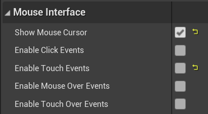
DemoPlayerController Settings
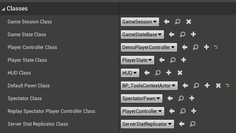
DemoGameMode Settings
Finally in the Project Settings dialog, I configured the Default GameMode to be our DemoGameMode Blueprint, and DefaultMap to the the Editor and Game startup map. I also added various actions in the Input section, I showed a screenshot of these settings above, in the description of AToolsContextActor. And finally in the Packaging section, I added two paths to Materials to the Additional Asset Directories to Cook section. This is necessary to force these Materials to be included in the built Game executable, because they are not specifically referenced by any Assets in the Level.

Packaging settings - these force Material assets to be included in the built game
RuntimeGeometryUtils Updates
In my previous tutorials, I have been accumulating various Runtime mesh generation functionality in the RuntimeGeometryUtils plugin. To implement this tutorial, I have made one significant addition, URuntimeDynamicMeshComponent. This is a subclass of USimpleDynamicMeshComponent (SDMC) that adds support for collision and physics. If you recall from previous tutorials, USimpleDynamicMeshComponent is used by the Modeling Mode tools to support live previews of meshes during editing. In this context, SDMC is optimized for fast updates over raw render performance, and since it is only used for “previews”, does not need support for collision or physics.
However, we have also been using SDMC as a way to render runtime-generated geometry. In many ways it is very similar to UProceduralMeshComponent (PMC), in that respect, however one significant advantage of PMC was that it supported collision geometry, which mean that it worked properly with the UE raycast/linetrace system, and with the Physics/Collision system. It turns out that supporting this is relatively straightforward, so I created the URuntimeDynamicMeshComponent subclass. This variant of SDMC, I guess we can call it RDMC, supports simple and complex collision, and a function SetSimpleCollisionGeometry() is available which can take arbitrary simple collision geometry (which even PMC does not support). Note, however, that currently Async physics cooking is not supported. This would not be a major thing to add, but I haven’t done it.
I have switched the Component type in ADynamicSDMCActor to this new Component, since the functionality is otherwise identical, but now the Collision options on the base Actor work the same way they do on the PMC variant. The net result is that previous tutorial demos, like the bunny gun and procedural world, should work with SDMC as well as PMC. This will open the door for more interesting (or performant) runtime procedural mesh tools in the future.
Using ModelingMode Tools at Runtime
It’s taken quite a bit of time, but we are now at the point where we can expose existing mesh editing Tools in the MeshModelingToolset in our Runtime game, and use them to edit selected URuntimeMeshSceneObject’s. Conceptually, this “just works” and adding the basic ability for a Tool to work only requires registering a ToolBuilder in AToolsFrameworkDemoGameModeBase::RegisterTools(), and then adding some way (hotkey, UMG button, etc) to launch it via the URuntimeToolsFrameworkSubsystem::BeginToolByName(). This works for many Tools, for example PlaneCutTool and EditMeshPolygonsTool worked out-of-the-box.
However, not all Tools are immediately functional. Similar to the global ToolTargetTargetFactory system, various small design decisions that likely seemed insignificant at the time can prevent a Tool from working in a built game. Generally, with a bit of experimentation it is possible to work around these problems with a small amount of code in a subclass of the base Tool. I have done this in several cases, and I will explain these so that if you try to expose other Tools, you might have a strategy for what to try to do. If you find yourself stuck, please post in the Comments with information about the Tool that is not working, and I will try to help.
Note that to make a Tool subclass, you will also need to make a new ToolBuilder that launches that subclass. Generally this means subclassing the base Builder and overriding a function that creates the Tool, either the base ::BuildTool() or a function of the base Builder that calls NewObject<T> (those are usually easier to deal with).
In several cases, default Tool Settings are problematic. For example the URemeshTool by default enables a Wireframe rendering that is Editor-Only. So, it is necessary to override the Setup() function, call the base Setup(), and then disable this flag (There is unfortunately no way to do this in the Builder currently, as the Builder does not get a chance to touch the Tool after it allocates a new instance).
Tools that create new objects, like UDrawPolygonTool, generally do not work at Runtime without modification. In many cases the code that emits the new object is #ifdef’d out, and a check() is hit instead. However we can subclass these Tools and replace either the Shutdown() function, or an internal function of the Tool, to implement the new-object creation (generally from a FDynamicMesh3 the Tool generated). URuntimeDrawPolygonTool::EmitCurrentPolygon() is an example of doing this for the UDrawPolygonTool, and URuntimeMeshBooleanTool::Shutdown() for the UCSGMeshesTool. In the latter case, the override performs a subset of the base Tool code, as I only supported replacing the first selected Input object.
These are the two main issues I encountered. A third complication is that many of the existing Tools, particularly older Tools, do not use the WatchProperty() system to detect when values of their UInteractiveToolPropertySet settings objects have been modified. Instead of polling, they depend on Editor-only callbacks, which do not occur in a built game. So, if you programmatically change settings of these PropertSets, the Tool will not update to reflect their values without a nudge. However, I have coupled those “nudges” with a way to expose Tool Settings to Blueprints, which I will now explain.
Blueprint-Exposed ToolPropertySets
One major limitation of the Tools Framework in 4.26 is that although it is built out of UObjects, none of them are exposed to Blueprints. So, you cannot easily do a trivial thing like hook up a UMG UI to the active Tool, to directly change Tool Settings. However if we subclass an existing Tool, we can mark the subclass as a UCLASS(BlueprintType), and then cast the active Tool (accessed via URuntimeToolsFrameworkSubsystem::GetActiveTool()) to that type. Similarly we can define a new UInteractiveToolPropertySet, that is also UCLASS(BlueprintType), and expose new UProperties marked BlueprintReadWrite to make them accessible from BP.
To include this new Property Set, we will then subclass the Tool ::Setup() function, call the base-class ::Setup(), and then create and register our new PropertySet. For each property we will add a WatchProperty() call that forwards changes from our new PropertySet to the base tool Settings, and then if necessary call a function to kick off a recomputation or update (for example URuntimeMeshBooleanTool will have to call Preview->InvalidateResult()).
One complication is enum-valued Settings, which in the Editor will automatically generate dropdown lists, but this is not possible with UMG. So, in those cases I used integer UProperties and mapped integers to enums myself. So, for example, here is all the PropertySet-related code for the URuntimeDrawPolygonTool of UDrawPolygonTool (I have omitted the EmitCurrentPolygon() override and new ToolBuilder that I mentioned above). This is a cut-and-paste pattern that I was able to re-use in all my Tool overrides to expose Tool Properties for my UMG UI.
UENUM(BlueprintType)
enum class ERuntimeDrawPolygonType : uint8
{
    Freehand = 0, Circle = 1, Square = 2, Rectangle = 3, RoundedRectangle = 4, HoleyCircle = 5
};

UCLASS(BlueprintType)
class RUNTIMETOOLSSYSTEM_API URuntimeDrawPolygonToolProperties : public UInteractiveToolPropertySet
{
    GENERATED_BODY()
public:
    UPROPERTY(BlueprintReadWrite)
    int SelectedPolygonType;
};

UCLASS(BlueprintType)
class RUNTIMETOOLSSYSTEM_API URuntimeDrawPolygonTool : public UDrawPolygonTool
{
    GENERATED_BODY()
public:
    virtual void Setup() override;

    UPROPERTY(BlueprintReadOnly)
    URuntimeDrawPolygonToolProperties* RuntimeProperties;
};

void URuntimeDrawPolygonTool::Setup()
{
    UDrawPolygonTool::Setup();

    // mirror properties we want to expose at runtime
    RuntimeProperties = NewObject<URuntimeDrawPolygonToolProperties>(this);
    RuntimeProperties->SelectedPolygonType = (int)PolygonProperties->PolygonType;
    RuntimeProperties->WatchProperty(RuntimeProperties->SelectedPolygonType,
        [this](int NewType) { PolygonProperties->PolygonType = (EDrawPolygonDrawMode)NewType; });

    AddToolPropertySource(RuntimeProperties);
}
ToolPropertySet Keepalive Hack
One major hitch I ran into in trying to get the MeshModelingToolset Tools to work in a built game is that it turns out that they do something…illegal…with UObjects. This really gets into the weeds, but I’ll explain it briefly in case it is relevant to you. I previously mentioned that UInteractiveToolPropertySet is used to expose “Tool Settings” in a structured way in nearly all the Tools. One desirable property of a system like this is to be able to save the state of Settings between Tool invocations. To do this, we can just hold on to an instance of the Property Set itself, but we need to hold it somewhere.
Various Editor systems do this by holding a pointer to the saved settings UObject in the CDO of some other UObject - each UObject has a CDO (Class Default Object) which is like a “template” used to construct additional instances. CDOs are global and so this is a handy place to put things. However, in the Editor the CDO will keep this UObject from being Garbage Collected (GC’d), but at Runtime, it will not! And in fact at Runtime, the Garbage Collector does a safety check to determine that this has not been done, and if it detects this, kills the game (!). This will need to be fixed in future versions of UE, but for this demo to function in a binary 4.26 build, we will need a workaround.
First, I had to disable the GC safety check by setting the global GShouldVerifyGCAssumptions = false in URuntimeToolsFrameworkSubsystem::InitializeToolsContext(). This prevents the hard kill, but the saved PropertySets will still be Garbage-Collected and result in crashes later, when the Tool tries to access them and assumes they still exist. So, in the URuntimeToolsFrameworkSubsystem::OnToolStarted() event handler, the AddAllPropertySetKeepalives() function is called, which iterates through the CDOs of all the registered PropertySet UObjects of the new Tool, and adds these “saved settings” UObjects to a TArray that will prevent them from being GC’d.
This is…a gross hack. But fully functional and does not appear to have any problematic side-effects. But I intend to resolve the underlying architectural issues in the future.
User Interface
The point of this tutorial was to demonstrate at-runtime usage of the Interactive Tools Framework and Mesh Modeling Toolset, not to actually build a functional runtime modeling tool. However, to actually be able to launch and use the Tools for the demo, I had to build a minimal UMG user interface. I am not an expert with UMG (this is the first time I’ve used it) so this might not be the best way to do it. But, it works. In the /ToolUI subfolder, you will find several UI widget assets.
ToolTestUI is the main user interface, which lives in the upper-left corner, there is an image below-right. I described the various Tool buttons at the start of the Tutorial. The Accept, Cancel, and Complete buttons dynamically update visibility and enabled-ness, based on the active Tool state, this logic is in the Blueprint. Undo and Redo do what you expect, and the World button toggles between World and Local frames for any active Gizmos. This UI is spawned on BeginPlay by the Level Blueprint, below-right.

There are also several per-tool UI panels that expose Tool settings. These per-Tool UI panels are spawned by the ToolUI buttons after they launch the Tool, see the ToolUI Blueprint, it’s very straightforward. I have only added these settings panels for a few of the Tools, and only exposed a few settings. It’s not really much work to add settings, but it is a bit tedious, and since this is a tutorial I wasn’t too concerned with exposing all the possible options. The screenshots below are from the DrawPolygonToolUI, showing the in-game panel (left) and the UI Blueprint (right). Essentially, on initialization, the Active Tool is cast to the correct type and we extract the RuntimeProperties property set, and then initialize all the UI widgets (only one in this case). Then on widget event updates, we forward the new value to the property set. No rocket science involved.
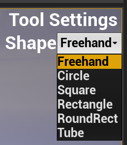
sincere Apologies for the terrible UI layout and sizing.
Final Notes
I have had many people ask about whether the UE Editor Modeling Mode Tools and Gizmos could be used at Runtime, and my answer has always been “well, it’s complicated, but possible”. I hope this sample project and write-up answers the question! It’s definitely possible, and between the GeometryProcessing library and MeshModelingToolset tools and components, there is an enormous amount of functionality available in UE4.26 that can be used to build interactive 3D content creation apps, from basic “place and move objects” tools, to literally a fully functional 3D mesh sculpting app. All you really need to do is design and implement the UI.
Based on the design tools I have built in the past, I can say with some certainty that the current Modeling Mode Tools are probably not exactly what you will need in your own app. They are a decent starting point, but really what I think they provide is a reference guide for how to implement different interactions and behaviors. Do you want a 3D workplane you can move around with a gizmo? Check out UConstructionPlaneMechanic and how it is used in various Tools. How about drawing and editing 2D polygons on that plane? See UCurveControlPointsMechanic usage in the UDrawAndRevolveTool. An interface for drawing shortest-edge-paths on the mesh? USeamSculptTool does that. Want to make a Tool that runs some third-party geometry processing code, with settings and a live preview and all sorts of useful stuff precomputed for you? Just subclass UBaseMeshProcessingTool. Need to run an expensive operation in a background thread during a Tool, so that your UI doesn’t lock up? UMeshOpPreviewWithBackgroundCompute and TGenericDataBackgroundCompute implement pattern, and Tools like URemeshMeshTool show how to use it.
I could go on, for a long time. There are over 50 Tools in Modeling Mode, they do all sorts of things, far more than I could possibly have time to explain. But if you can find something close to what you want to do in the UE Editor, you can basically copy the Tool .cpp and .h, rename the types, and start to customize it for your purposes.
So, have fun!