Procedural Mesh Blueprints in UE4.26

no static meshes were cooked in the making of this level. Click to play video.

In my previous tutorial, I showed you how to do runtime mesh manipulation in Unreal Engine 4.26 using various components (UStaticMeshComponent, UProceduralMeshComponent, and USimpleDynamicMeshComponent) by way of the GeometryProcessing plugin’s mesh editing capabilities and a sort of “wrapper” Actor called ADynamicMeshBaseActor. An obvious thing that you might want to use this machinery for is to do procedural geometry generation, either in-Editor or in-Game. And since ADynamicMeshBaseActor exposed Blueprint functions for things like mesh generators, Mesh Booleans with another ADynamicMeshBaseActor, and so on, one could imagine building up a procedural system where you generate Actors and combine them to build up complex geometry.

Here’s the problem though: Actors are expensive. Say you want to do something like use an L-System to create plants, or buildings, or whatever. These systems tend to involve lots of small meshes. Making an Actor for each of those small meshes would be…painful.

So, in this tutorial I’m going to show you one way to implement a more effective procedural mesh generation system in Blueprints. I’m not sure this approach is the best way to do it, and it has some serious pitfalls. But the result is that the small level you see on the right is 100% generated by Blueprints - there is not a single static mesh in this project. All the geometry is built up by combining simple primitives, doing operations like Booleans and mesh-wrapping and applying displacement noise, and there is even a simple all-in-Blueprints scattering system for placing rocks on the asteroids. The textures are not procedural, I made them in Quixel Mixer. But they are applied without UV maps, so that’s kinda procedural! And I threw in a little Niagara particle system at the end, to spice up your escape from the Asteroid.

(Mandatory Disclaimer: your author, Ryan Schmidt, is an employee of Epic Games. However, gradientspace.com is his personal website and this article represents his personal thoughts and opinions. In particular, this tutorial code and content is not part of Unreal Engine, and it isn’t supported by Epic Games.)

Getting and Running the Sample Project

Before we begin, this tutorial is for UE 4.26, currently in Preview release (Preview 7 at time of writing). You can install the Preview binaries from the Epic Games Launcher.

The project for this tutorial is on Github in UnrealProceduralMeshesDemo repository (MIT License). I did not include this in the same repository as my previous tutorials because there are ~100mb of binary files. In UE 4.26 this project will probably only work on Windows due to the inclusion of the DynamicSDMCActor class in the RuntimeGeometryUtils plugin. However I did not use any DynamicSDMCActors in this project, so you should be able to make it this demo work on OSX/Linux by deleting the DynamicSDMCActor .cpp and .h files - see the notes at the end of the previous tutorial (If you try that and it works, please send me a note so I can mention it here).

Once you are in the top-level folder, right-click on ProceduralMeshesDemo.uproject in Windows Explorer and select Generate Visual Studio project files from the context menu. This will generate ProceduralMeshesDemo.sln, which you can use to open Visual Studio. You can also open the .uproject directly in the Editor (it will ask to compile), but you probably will want to refer to the C++ code for this tutorial.

Build the solution and start (press F5) and the Editor should open into the sample map. You can test the project in PIE using the large Play button in the main toolbar, or click the Launch button to build a cooked executable. This will take a few minutes, after which the built game will pop up in a separate window. Try to escape the level! You’ll have to press Alt+F4 to exit as there is no menu/UI.

UGeneratedMesh

At the end of the last tutorial, ADynamicMeshBaseActor had some basic Blueprint functions you could use to do single mesh operations, like subtract another Actor, and so on. But to do real mesh generation, we need lots of temporary meshes. Consider something trivial like a “stairs generator”. In it’s simplest form, you would make a box, and then append a bunch of translated copies of that box, each shifted up-and-forward from the last. What I want to be able to do is have a BP_ProceduralStairs Actor, that has parameters for # of steps, width, height, etc, and it’s Blueprint does the mesh generation.

To do this kind of thing, we’re going to need temporary meshes. I want to make a temporary mesh, append a bunch of other meshes to it (which might be temporary meshes themselves), and then transfer that mesh to my ADynamicMeshBaseActor’s Source Mesh. So the question is, how to handle the temporary meshes in Blueprints? In Normal C++ we would just make FDynamicMesh3 objects, use them, and throw them away. But in Blueprints, we can only “use” the meshes by passing them between Blueprint functions. And to pass data between BP Functions, we either have to have them be UStructs or UObjects.

The issue with using UStructs is that Blueprints pass UStructs by value, and are very liberal with making copies of UStructs. So what that means is, if we put our FDynamicMesh3 inside a UStruct, it gets copied. A lot. There are ways to cheat to avoid the copies, like stuffing non-UProperty pointers inside the structs, but to use the cheats safely means that the person making the Blueprints has to understand what going to happen in C++. This is a Bad Idea.

So, our other option is a UObject. UObjects are much heavier than UStructs, and they are managed via garbage collection. What that means is, when a UObject is no longer referenced by any UProperties, it will be deleted (eventually). This garbage collection is going to cause some complications. But otherwise, this approach basically works. I have created a class UGeneratedMesh that is similar to the core of ADynamicMeshBaseActor - it has a FDynamicMesh3, as well as FDynamicMesh3AABBTree and TFastWindingTree for spatial queries.

What it doesn’t have is a Material, Transform, or any of that stuff. It’s just a container for a mesh, with a set of UFunctions to manipulate that mesh. The set of functions is quite large, it includes a bunch of primitive generation functions (Box, Sphere, Cylinder, Cone, Torus, Revolves, and Extrudes), functions to Append and Boolean other UGeneratedMeshes, Cut with a plane, Mirror, Solidify, Simplify, Transform, Recompute Normals, and various Spatial Query functions. It can do a lot of things! And you can spawn them in Blueprints as needed, to do node-graph-style geometry creation.

My basic stacked-boxes Stairs Generator is below. This is all happening in the Construction Script on an ADynamicMeshBaseActor Blueprint called BP_ProceduralStairs in the sample project. I have two temporary meshes, Step Mesh and Stairs Mesh. The Append Box function adds a box to the Step Mesh, and then the Append Tiled function adds Step Mesh to Stairs Mesh multiple times, applying the input Transform each repetition. Finally Copy from Mesh is a function of the ADynamicMeshBaseActor, that copies the UGeneratedMesh geometry into the Actor, which then goes on to it’s Component (I will use ProceduralMeshComponent for everything in this tutorial, we’ll get to that).

All the parameters above are exposed on the Actor, so in the Editor I can select a BP_ProceduralStairs and change it’s various dimensions and number of steps in the Actor Details panel.

Our Nemesis: Garbage Collection

There is one fly in the ointment here, though. In the BP screenshot above, I cropped off the top. That’s where I need to create the UGeneratedMesh instances for StepMesh and StairsMesh. The standard way to do this would be to use the BP version of the C++ NewObject<> function, which spawns a new UGeneratedMesh UObject. The Blueprint nodes below-left do that (click to enlarge). This works fine, until you open up the Task Manager and look at memory usage as you drag one of the parameters in the Details Panel. Look at it go - hundreds of megabytes in a few seconds!

ProceduralMeshes_ConstructScript_NewObject.gif

What is happening here is that the temporary UObject meshes we spawned with Construct Generated Mesh are not deleted when the Construction Script completes. They become unreferenced, but they will hang around until the Garbage Collector (GC) runs, which is about once a minute in UE4.26. And sure enough, if you wait for a while, memory usage will drop back down. But this is not acceptable. We could force the GC to run, but this is not a good practice, and creating and then destroying all these UObjects is a lot of overhead.

Generated Mesh Pooling

What to do? Well, this is not a new problem. It comes up all the time, and particularly in procedural systems where you are going to do the same thing over and over as the user interactively changes some parameter. The general way to address this is Caching of some kind or other, and for this specific situation the standard strategy is Pooling. Which means, basically, re-use the things you have already created/allocated instead of making new ones all the time.

Re-using UObjects is a bit tricky in Blueprint Construction Scripts, where we ideally want to do our mesh generation (otherwise it will not be visible in the Editor). We can’t just add some generated-mesh pool UObject in the Construction Script because it will get re-created on each run. So, I put it in the ADynamicMeshBaseActor. There is a UGeneratedMeshPool class, and a UProperty instance of this, but it is not exposed to Blueprints directly. Instead there is a BP function ADynamicMeshBaseActor::AllocateComputeMesh() which will give you a UGeneratedMesh you can use, either by allocating a new one or providing one from the pool. So now our Blueprint looks like below, and we see that memory usage stays reasonable as we edit an instance of the BP_ProceduralStairs Actor:

ProceduralMeshes_ConstructScript_ComputeMeshPool.gif

But, we’re actually not done yet. If you look up at the Stairs Generator BP, you’ll see that the Exec path also goes off to the right. What’s over there? Well, generally when you do Pooling you have to explicitly give any objects you took back to the Pool, and it’s no different here. ADynamicMeshActor also has several functions to return the UGeneratedMesh’s we have taken ownership of. These must be called at the end of the BP, otherwise the mesh will hang around forever! The screenshot below shows two possible paths, there is a Release Compute Meshes function that lets you explicitly release meshes (there is also Release Compute Mesh for a single mesh), as well as a simpler Release All Compute Meshes function that tells the Pool to take back all the meshes it has given out. I tend to use this one when generating meshes in construction scripts, as it requires the least effort, but be aware that it means you can’t hold on to any of the meshes.

This “Return to Pool” mechanism is the one big gotcha of this UGeneratedMesh architecture. I haven’t figured out a way around it. If you forget to release your compute meshes, things could spiral out of control quickly! So, to try to avoid catastrophe, if the pool grows to over 1000 UGeneratedMeshes it will clear the pool and run garbage collection.

DynamicMeshBaseActor Improvements

DynamicMeshActorProps.png

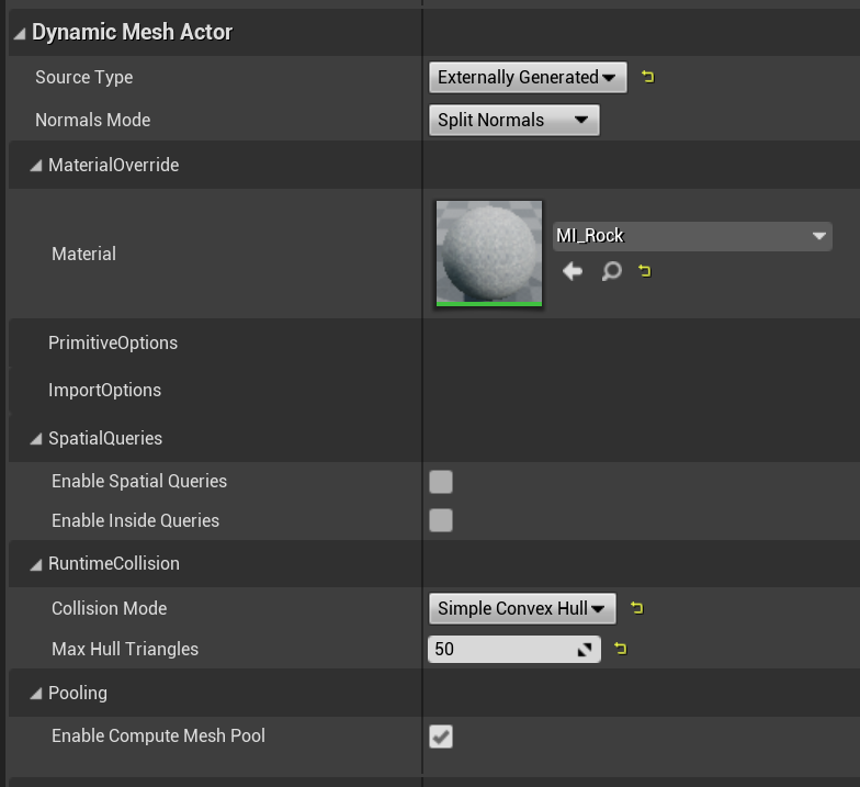
This tutorial will use the ADynamicMeshBaseActor I created in the previous tutorial to represent procedural meshes in the Level. I have made some improvements, though. First of all, I grouped the various UProperties under a DetailsView category called “Dynamic Mesh Actor”. I have added a new Source Type called Externally Generated. This tells the Actor that you will populate it’s Source Mesh yourself - if you don’t set it to this value, then it will overwrite your generated mesh with a Primitive or Import.

I also exposed a new Runtime Collision mode named Simple Convex Hull. When set to this mode, the DynamicPMCActor subclass will calculate convex hull “simple collision” for the mesh whenever it is updated. This convex hull will optionally be simplified to the Max Hull Triangles triangle count (set to zero to use the full hull). If you use this mode, then it is possible to enable Simulate Physics on the ProceduralMeshComponent and it will work!

We will use this option in a few places. Note, however, that generating the convex hull can be very expensive if the input mesh is large - ie several seconds if you have many thousands of triangles. It might make sense to have some thresholds, ie don’t compute the hull if the mesh is too large, or randomly sample a subset of vertices. I haven’t done any of that, but I would take a PR!

Note that I exclusively used DynamicPMCActor in this project. This is because only the ProceduralMeshComponent supports runtime cooking of Simple or Complex collision, and only with PhysX (the default physics library in UE 4.26 - for now!).

UGeneratedMesh Procedural Mesh Generation API

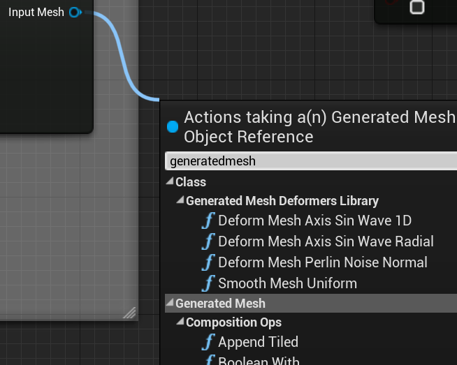
I won’t say much about the actual UGeneratedMesh Blueprint API, you can skim the header or browse the Generated Mesh category in the BP Editor (search “generatedmesh” in the BP function search bar) to see what is available. There is no particular strategy for completeness, I implemented what I needed to make the tutorial. Most of the functions are just wrappers around calls to the GeometryProcessing plugin.

One slightly unusual thing I did in the BP functions is have most of them return a UGeneratedMesh that is actually just the input mesh. It’s very important to note that this is not a copy. That’s why the output pin is labeled “Input Mesh”. Because a lot of the mesh processing is a sequence of functions applied to the same UObject, I found that this let me make BPs which were much clearer to read, vs having a far-away output feeding multiple inputs. However these output pins are optional and you don’t have to use them!

Another important note: there are not many safety checks in these functions. If you pass in arguments that will produce a huge multi-gigabyte mesh, the code will happily do it and you will have to kill the Editor. It’s kind of tricky to put in these kinds of limits, because what one person considers reasonable may be an eternity to another.

Blueprint Function Libraries

GEneratedMesh_deformers_library.png

I have placed most of the mesh editing functions directly on UGeneratedMesh. However, this strategy will lead to enormous classes which can be difficult to manage. It also doesn’t work to “extend” the base class with additional functions, which is particularly a challenge if you have your own third-party libraries and you want to use them in some BP function implementations. To handle this kind of situation, we can use a Blueprint Function Library. Making a BP Library is very simple, just define a C++ class that subclasses UBlueprintFunctionLibrary, and then add static UFunctions that are BlueprintCallable. Those functions will then be available in the BP Graph Editor.

I did this for the various mesh deformers that are used below (Sin Wave Displacement, Perlin Noise, Mesh Smoothing, etc). The static UFunctions functions are in the UGeneratedMeshDeformersLibrary class. Organizing things this way allows you to add your own functions that operate on a UGeneratedMesh, and keep your C++ code better-organized (I should have done more of the UGeneratedMesh API this way!)

Blueprint Procedural Mesh Generators

Ok, on to the tutorial. I have already explained the Stairs generator above. In the tutorial there are various other Procedural Mesh BP Actors that I will briefly explain here

BP_Wall

BP_Wall.gif

This Blueprint generates a basic rectangular box with configurable width/height/depth, and an optional angled top, created using a plane cut. The angled top allows this BP_Wall to also be used for creating ramps. There really is not much to it. Most of the nodes below are converting the input parameters into the necessary input vectors, rotations, transforms, and so on. So far I have found that this part tends to be more work than setting up the actual mesh operations. That said, I’m also not a Blueprint guru so maybe there are more efficient ways to accomplish some of these basic geometric constructions.

The only thing I wanted to point out below is the Set To Face Normals call. In most of the editing operations, I am not automatically recomputing normals. This is to avoid the cost of repeated normal computation if you are chaining multiple operations together. Note that Copy from Mesh has a Recompute Normals boolean. This does work, but it does not have the ability to compute normals with creases based on a threshold angle, which can be done with the UGeneratedMesh function SetToAngleThresholdNormals (which is not necessary on a wall like this, where Face Normals are sufficient, but I used it in various others below)

BP_Rock

BP_RockEmitter.gif

This is another relatively simple generator, that creates a reasonable rock or boulder by displacing the vertices of a sphere using Perlin Noise. Hard Normals are then computed with an angle threshold, which produces some sharp edges and, combined with a nice triplanar texture, makes for a reasonably convincing rock. This is quite a cheap generator, and with a bit of additional effort the rocks could be randomly scaled, and/or multiple frequencies of Noise could be used to produce a wider range of shapes. Note that the Noise is defined by an explicit RandSeed parameter - if you don’t change this, you’ll get the same rock every time. In this kind of procedural generator, we generally want reproducible results so it is necessary to use explicit random seeds.

For these rocks, I have set the Collision Mode to Simple Convex Hull in the Dynamic Mesh Actor properties. This allows the rocks to be simulated, which is why they can drop out of the pipe and roll down the stairs.

Note that in the BP below, the construction script just calls a BP-defined function called Generate Rock. This is a useful way to organize procedural mesh generators, and allows for “sharing code” between the Construction Script and Event Graph (a common thing to want in procedural generators).

The pipe the rocks fall out of is also procedurally generated in BP_RockEmitter, by creating two cylinders and then subtracting a third. There is nothing particularly new in that generator that isn’t in the others, so I did not include it here. BP_RockEmitter also has some Tick functionality, as it spawns new instances of BP_Rock at regular intervals, but this is pretty standard Blueprint gameplay stuff so I won’t explain it here.

BP_DynamicBridge

BP_Walkway.gif

In the tutorial project level, once you’ve made it past the barrier wall, you’ll have to correctly time a run across a walkway that cycles back and forth to the far platform, as shown on the right. This is a procedural mesh being regenerated each frame, with the “bridge length” parameter being driven based on elapsed game time.

The geometry generation is not that complex, just a box with two Sin wave deformers applied to it. However the BP is structured somewhat differently than BP_Rock, in a way that I think is better. The geometry is created in a BP Function called Generate Bridge. However instead of allocating and releasing it’s own compute mesh, Generate Bridge takes the UGeneratedMesh as an argument, and returns it at the end of the function. This means that if you wanted to re-use this code, you can easily cut-and-paste it into any other BP without having to worry about the Copy from Mesh and Release All Compute Meshes at the end of Generate Rock above (which might conflict with other geometry generation you want to do).

Another benefit to putting the generation code in a BP Function is you can then easily run the same code in-Editor and in-Game. The Construction Script (below-middle) and the Event Graph Tick version (at the bottom) are basically the same, except for the time-dependent animation of the length parameter.

BP_BlobGenerator

BP_BlobGenerator.gif

The Blueprint that creates the two large asteroid pieces is BP_BlobGenerator, and it has quite a lot going on. I won’t fully explain every node, it but here’s a simplified description of what happens along the exec flow below

  1. Create a mesh called Subtract Shape (a sphere in this case)

  2. Create another Sphere and deform it with two Sin Wave deformers, this is our final Accumulated mesh we will build up

  3. For Loop to repeat the following “NumBlobs” times

    1. Generate a random point on a sphere

    2. find the closest point on the Accumulated mesh

    3. subtract the Subtract Shape from the Accumulated mesh at that point, with a random scale

  4. Update the Actor’s source mesh

  5. Optionally apply the Make Solid BP function below

By default, BP_BlobGenerator has no collision enabled, however the asteriods in the tutorial level are configured to use Complex as Simple collision. This works quite well to create landscape-type elements that are not too high-resolution. In the level, I increased the simplification triangle count to 4000, because at large scale things felt a bit too triangulated. A pass of mesh smoothing might also have helped to reduce that.

The Make Solid function is straightforward, basically we are going to copy the current Source Mesh from the Actor, call the Solidify function, apply Perlin noise displacement if necessary, and then Simplify the result and re-update the Actor Source Mesh. This generates a more compelling rock-like/organic object, by removing all the sharp creases and “perfect” geometry.

BP_BlobGenerator_SolidyFunc.png

One issue with using this BP in practice is that the Solidify and Simplify functions are (relatively) slow, for real-time use. This is all vastly more expensive than BP_Rock, for example. So, in practice when I am positioning and configuring one of these Actors, I would disable the Solidify setting in the “Blob Generator” DetailsView properties, and then toggle it on to see the final result. However I did one other thing in this BP, which is to enable the “Call in Editor” flag on the MakeSolid BP function (shown below-right). This leads to the BP Function being exposed as a button labeled “Make Solid” in the Blob Generator Details panel section (shown below-left). If you click that button, the Make Solid function will be applied. This is why I in the Make Solid function I initialized a GeneratedMesh from the current Actor Source Mesh - so that it can be called without re-running the Construction Script.

 
BP_BlobGenerator_CallInEditor_Button.png
 

These kinds of UI-exposed functions are extremely useful as a way to extend the capabilities of an Actor in the Editor. For example it might be nice to have a button on the ADynamicMeshActorBase that could emit a new StaticMeshActor - it would effectively turn these Procedural Mesh BPs into asset authoring Tools in the Editor. Maybe something to tackle in the future. However, do be aware that the next time the Construction Script runs it will wipe out any result created by incrementally updating the Source Mesh!


BP_SpaceShip

At the end of the tutorial video, the character jumps off the edge of the asteroid, lands on a ship, and flies away. Making this ship was the most time-consuming part of creating the demo, but in many ways it’s both visually and technically the least interesting. The BP is below, you can click to see a larger version, but you’ll discover that’s really just a straight-ahead generate-primitives-and-append-them situation. The generator could be parameterized in many ways, which might make it more useful. But I think I would have been able to hand-model a more interesting ship in much less time.

This BP does have a nice Niagara particle system attached, though, that emits particles from the rear engine when they fire up. I followed the “Create a GPU Sprite Effect” tutorial on from the UE4 documentation to start, and then made changes. It was very straightforward and looks pretty good, I think.


BP_RockScatter

BP_RockScatter_demo.gif

This Actor is the most complex in this tutorial as it isn’t really a single “object”, but rather a generator for a set of rocks covering the asteroid surface. The basic idea here is not complicated - I am going to generate random points on a 3D plane above the asteroid, shoot rays downwards, and if the rays hit a relatively flat spot, I’ll add a new randomly-deformed rock at that location.

That might sounds costly, but actually this actor is surprisingly inexpensive - it updates very quickly as I drag it in the Editor viewport. This is because the computation involved amounts to a raycast and then a mesh copy. It’s much cheaper than even a single mesh boolean, let alone voxel operations or simplification. All the rocks are accumulated into a single mesh, so this doesn’t add a tick or draw call per-rock (however it also means there is no instanced rendering). That said, if I crank up the rock count, things will start to get chunky (on my quite powerful computer, 50 rocks is interactive but 200 takes a second or so to update).

Note that this definitely isn’t the most efficient way to implement scattering like this. At minimum all the ray-shooting and mesh generation/accumulation could easily be ported to a single C++ UFunction, and much of it done in parallel. But it’s kind of nice to prototype it in Blueprints, where an artist can easily go in and make changes.

You might note in the gif above there is a yellow box that is moving with the scattered rocks. This is a Box Collision component that I added in the Actor to define the scattering bounds, as shown in the BP editor screenshot to the right. The ray origin points are randomly generated on the top face of the box, and shot down the -Z axis. The box dimensions/etc could have been done with BP parameters, but having a visual box is a nice design guide and helps with debugging.

The scattering in the Actor BP is computed in the Do Scatter function, the Construction Script just calls this, like we saw in other examples above. Most of this BP is actually just generating the ray origin and mapping between coordinate systems. Basically we generate one rock and then inside the For loop, at each valid intersection point, we apply a random rotation and scale to break up the repetition. Although Append Tiled is used, it’s called once for each rock, with 1 repeat - so in this context it’s just a way to append a single mesh, because we don’t have an Append Once function. Finally in the bottom-right we return the accumulated Scatter Objects mesh.

BP_RockScatter_targets.png

One question is, what to scatter on. We could have used world linetraces to find hits, but then we would have had to filter out all the non-asteroid level elements. Instead I used the ADynamicMeshBaseActor spatial query function IntersectRay. The BP_RockScatter has a public array UProperty of ADynamicMeshBaseActor targets, as shown on the right. The Find Intersection Point BP function (pasted below) calculates the nearest ray-intersection point on each of these objects and returns the nearest point. Although I have hardcoded the ray direction in this point, that could easy be exposed as an argument, making this a very general BP function (that doesn’t rely on physics!)

One important note about working with this BP in the Editor. The rocks only update when the Construction Script runs. So, if you change the Asteroids, you need to force the Scattering to be recomputed by changing a setting of the Actor instance (ie, “jiggle it” a bit, change the Scatter Count, etc).

UVs and Triplanar Textures

I have avoided the question of UVs so far, because UVs potentially make all this procedural-mesh stuff a lot more complicated. The basic shape-generator functions for spheres, boxes, toruses, etc, all generate decent UVs. The underlying generators have more UV options that could be exposed. Boolean operations will combine UVs properly, and perations like Plane Cut will (for example) generate UVs on the cut surface, and there are controls for those UVs in the underlying C++ code (also not BP-exposed here). However none of these operations will update the UV Layout, ie make sure that islands are unique/etc. And there is no way (currently) to recompute UVs for an object after something like the Solidify operation. (This can be done in the Editor, but it requires calls to Editor-Only code, and only works on Windows currently).

This limits the options for texturing, but again, in a procedural context this is all pretty common. If you want to generate procedural worlds, you aren’t going to be hand-painting them. The most basic procedural texturing one can do is simply to apply tiled UV maps, based on the UV set. This can work surprisingly well if the “scale” of the UV islands on the mesh are all relatively similar, however (for example) if you subtract a small sphere from a big one, this won’t be the case by default. The UVs in the subtracted-small-sphere area will be denser, and so the texture pattern will be different sizes.

An alternative is to use local or world-space Projection. What this means at a conceptual level is, we take a geometric shape with known “good” UVs, eg like a plane/box/cylinder/sphere, and put the texture map on that shape. Then to find the color at a point on our detailed shape, we map that position onto the simple shape (eg by casting a ray, nearest point, etc) and use the color/etc at the mapped point. So for example with Planar Projection, to find the color for point P we would project P onto the tangent axes of the plane, ie U = Dot( P-PlaneOrigin, PlaneTangentX ) and V = Dot( P-PlaneOrigin, PlaneTangentY ), and then sample the Plane’s Texture Map at (U,V).

Planar Projection is cheap but only works if your surface is basically pointing at the plane, otherwise it just kind of smears out. A more complex version is TriPlanar Projection, where you have 3 planes and use the surface normal to choose which plane to project onto, or as a way to compute a blend weight between the 3 colors sampled from each plane. This works particularly well for things like rocks, cliffs, and so on. In UE there are special Material nodes to create TriPlanar texture, called WorldAlignedTexture, WorldAlignedNormal, etc (this technique does work for both world-space and local-space, despite the name). The Quixel website has an excellent tutorial on setting up these kinds of Materials. In this tutorial I have used TriPlanar materials extensively, for all the rocky surfaces. Quixel’s Megascans library has tons of great tileable textures to use with TriPlanars (all free if you are using UE4). And you can also use Quixel Mixer to create new ones - I made the textures in the tutorial sample by messing around with the Mixer sample projects.

Finally it is also possible to procedurally generate fully 3D materials, ie 3D patterns that the mesh “cuts through” to define the surface texture. These can work quite well if you are going to cut into the shape using booleans. I have used one of these for the destructible brick wall, but I won’t say this is necessarily the greatest example - I am a novice at creating UE Materials!

Gotchas, Pitfalls, Caveats, and so on

I quite enjoyed playing with procedural shape generators like this in the Editor. I’m not a great artist, so being able to generate shapes and mash them up let me build a level I probably would not have put in the effort to model by hand. But, I do want to be super clear that although the approach to procedural content generation that I have outlined here might be fine for a demo or small indie game, it won’t scale up to a large procedural world. There are some major problems.

For one, UProceduralMeshComponent is serialized in the Level. So every time I save the level, all my generated PMCActor meshes are being saved, and when I restart the Editor they are de-serialized, right before my Construction Scripts run and regenerate them all! It’s not only inefficient (it takes quite a long time), it also requires a lot of disk space - the AA_AsteroidLevel.umap file is 38MB, just for this small level. And if the content is all in the Level, you can’t have someone else working on it, as you can’t merge changes to the binary .umap file. So, saving and loading the Level is a bottleneck. (Note that this would not be an issue if the Actors were only spawned at runtime)

Second, I relied very heavily on Construction Scripts. This is mostly fine, as the objects are generally independent. However, it is a major problem for the BP_RockScatter scattering Actor. The issue is that this Construction script must run after the scripts for the Asteroids, or there is nothing for the raycasts to hit. However, it is not possible to explicitly specify the ordering of Construction scripts. So it’s easy for this to break. If you google you’ll find various tricks, like order of adding to the level, naming, etc, that can make this work, but these are not guarantees and the ordering could easily change in future Engine versions. If you wanted to build a complex sequence of procedural generators, with dependencies on eachother, this would not be possible to do with Construction scripts. It is possible to better handle these kind of dependencies at runtime, by making the generation dependent on events fired between Actors. But then you have to PIE to see what your generators are doing.

Third, it’s pretty easy to accidentally lock up the Editor when playing with these Blueprints. The computation all happens on the main thread, and cannot be interrupted, so if you do something that is going to take 20 minutes (or 20GB of RAM) to compute, you’ve just got to wait. In particular, dragging sliders in the Details panel is a problem, it tends to lock things up while it recomputes the BP for each slider update. I got in the habit of typing in new values instead of just scrubbing to see what happens, like you might in a Material.

Basically, we’re trying to wedge a procedural geometry dataflow graph into a system that was not designed for this. A real procedural node-graph system for doing expensive geometry operations has a very different underlying architecture than a runtime gameplay framework like Blueprints. For example, a procedural node-graph system usually automatically handles things like our mesh pool, caches expensive computations, evaluates nodes in parallel when possible, and so on. Then again, those DCC-tool node-graph systems don’t work at Runtime…

Wrapping Up

That’s it for this tutorial. If you make neat things with procedural meshes using the system I have developed here, please @ me on twitter (@rms80) with screenshots, comments, and suggestions, or send an email.

ArranLangmeadProcGenTrees.jpg

If you want to dive deeper into Procedural Content Authoring/Generation inside UE, I highly recommend watching the Getting Started with Procedural Mesh Generation twitch stream by Arran Langmead (twitter). In this video Arran explains how he builds a procedural tree generator using the basic UProceduralMeshComponent API (which allows you to build up meshes directly from vertex positions and triangle index arrays). There is an accompanying written article which walks through much of the same content on 80.lv. Unlike myself, Arran is a UE master and his tree sample can show you how to do awesome things like make procedural shaders and procedurally animate generated meshes with materials.

After I watched Arran’s video I realized there is so much more that could be added to UGeneratedMesh, particularly with vertex colors. I have not made any effort to support vertex colors. But, FDynamicMesh3 supports vertex colors, and it would not be difficult to add vertex color support so that (for example) vertex colors on different parts of a Boolean are preserved, or to add BP functions to calculate vertex colors from spatial fields, 3D noise, etc. Exciting!

Command-Line Mesh Processing with Unreal Engine 4.26

This is the first of several tutorials that will (hopefully) teach you how to do advanced Mesh/Geometry Processing with Unreal Engine. Past Gradientspace Tutorials focused on the open-source Geometry3Sharp library that I developed in C#, and demonstrated how to do things like Mesh Simplification, Remeshing, Implicit Surface Modeling, and so on. G3Sharp became quite powerful, I used it to create the Cotangent 3D printing tool, and helped others use it to build Archform (a tool for designing dental aligners) and NiaFit (for designing 3D printable prosthetics). Quite a few other developers seemed to like it, too.

However, ultimately C# became a limiting factor for G3Sharp. I really like coding in C#, but the performance cost can be high, and critical math libraries like sparse linear solvers are missing from the C# ecosystem. The thought of porting even more WildMagic/GTEngine code, it was just too much! So, in December 2018 I joined Epic Games and started a C++ port of G3Sharp. Thanks to the hard work of the UE Geometry Team, this library - the GeometryProcessing plugin - has now far surpassed G3Sharp in capability. So, I think it’s about time to start showing you how to use it.

In this tutorial, I am going to walk you through a single example that generates all the meshes in the image below. In doing so, we will cover the main content of most of the previous GradientSpace G3Sharp tutorials, but in C++, in Unreal Engine. To avoid any UE complexity in this intro tutorial, we’re going to do everything in a simple command-line tool. But keep in mind that everything we’re going to do is available both in the Editor, and in-game at Runtime.

(Mandatory Disclaimer: your author, Ryan Schmidt, is an employee of Epic Games)

Translation for Chinese users: https://zhuanlan.zhihu.com/p/343789879

Preliminaries / UE4 Setup

Click to Enlarge

One small hurdle we have to overcome is that binary UE4 engine installations cannot build command-line executables. So, we’ll need to use the UE4 source, which you can get on Github once you have joined the Epic Games Github Organization (click link for instructions - it’s free for anyone who accepts the UE4 license agreement). This tutorial depends on code only available in version 4.26 or later, so I suggest you use the 4.26 branch (https://github.com/EpicGames/UnrealEngine/tree/4.26) directly (this tutorial should also work against the Release branch by the time you read it).

The simplest thing to do (in my opinion) is to use the Download Zip option, available under the Code drop-down button (see image to the right). Download and unzip (this will require about 1.7 GB of disk space). After that, you’ll need to run the Setup.bat file in the top-level folder, which will download another ~11GB of binary files and then run an installer that unpacks that into another ~40 GB. Unfortunately there is no more compact variant. Time for coffee!

The code for this tutorial is available on GitHub in the gradientspace UnrealMeshProcessingTools repository (click for link), in a folder named CommandLineGeometryTest in the UE4.26 samples subfolder. Again, you can download a zip of the top-level repository (click for direct link), or you can sync with a git client, too.

Assuming you unzipped the UE repository into a folder named “UnrealEngine-4.26”, then you’ll need to copy or move the sample code folder UE4.26\CommandLineGeometryTest to the path UnrealEngine-4.26\Engine\Source\Programs\, as shown in the image on the right. This folder contains various other command-line tools and apps that UE uses. You might be able to put it in other places, but this is where I tested it from, and where the sample HoleyBunny.obj file paths are hardcoded relative to.

For reference, I created this sample project based on the BlankProgram command-line executable that is included with the Engine (you can see it in the list on the right). This is a minimal Hello-World example program and a good starting point for any command-line executable based on UE (eg for unit testing, etc). The only modification I had to make to get things to work was to add references to several of the modules in the GeometryProcessing plugin, in the CommandLineGeometryTest.Build.cs file:

PrivateDependencyModuleNames.Add("GeometricObjects");
PrivateDependencyModuleNames.Add("DynamicMesh");

If you wanted to use these modules in other projects, you will have to do the same. Note that many parts of the Engine are not immediately available in a command-line or “Program” target type. For example in BlankProgram the UObject system is not initialized. The GeometryProcessing plugin modules have minimal engine dependencies, and do not define UObjects, so this is not a problem for this tutorial. (It is possible to initialize various engine systems, see for example the SlateViewer program.)

click to enlarge

Once you have the files in the right place, run the top-level GenerateProjectFiles.bat file. This will generate a Visual Studio 2019 UE4.sln file. Oh, by the way, you probably want to have Visual Studio 2019 installed, if you are on Windows. If you are on Linux or OSX, there are .command/.sh versions of the batch files I mentioned above, and this tutorial should work on those platforms, too. (GeometryProcessing has already been used in shipping games on desktop, mobile, and console platforms!!)

Open up UE4.sln, and you will find a long list of projects in the Solution Explorer subwindow. Find our CommandLineGeometryTest project, right-click on it, and select the Set as Startup Project option that appears in the context menu. Then click the Start Debugging button or hit F5. This will build for a minute or so, then pop up a command-line dialog box and print a bit of info as the tutorial runs (should only be a few seconds, though).

Note that this is not a full build of UE4. Since we are building a simple command-line app, we don’t have any dependencies on the majority of the Engine, or the Editor. A full build would take much longer - from ~15 minutes on my 24-core Threadripper to well over 2 hours on my 4-core laptop. So, make sure you don’t do a “Build Solution” or “Rebuild All”, or you are in for a long wait.

Tutorial Files

The sample code contains just a few files, all the code we care about is in CommandLineGeometryTest.cpp. The CommandLineGeometryTest.Build.cs and CommandLineGeometryTest.Target.cs are configuration files for the CommandLineGeometryTest UE4 module, and the CommandLineGeometryTest.h is empty.

The GeometryProcessing module does not natively support any file I/O, so the DynamicMeshOBJReader.h and DynamicMeshOBJWriter.h are necessary to read/write OBJ mesh files. The OBJ Reader is just a wrapper around the tinyobjloader library (https://github.com/tinyobjloader/tinyobjloader, source is embedded) which constructs a FDynamicMesh3 (the mesh class we will use). The OBJ Writer is minimalist, but does the basics.

CommandLineGeometryTest.cpp just contains #includes and a main() function, and I'm going to paste the entire tutorial code below. We'll step through the blocks afterwards, but I think it's instructive to skim through it all first. In less than 150 lines, this code demonstrates normals calculation, sphere and box generators, Mesh AABBTree setup and queries (nearest-point and ray-intersection), appending meshes, fast-winding-number-based resampling, implicit morphological operations, mesh simplification, isotropic remeshing, mesh hole filling, and mesh booleans (twice) ((yes, MESH BOOLEANS zomg!!)) :

// import an OBJ mesh. The path below is relative to the default path that Visual Studio will execute CommandLineGeometryTest.exe,
// when using a normal UE4.26 auto-generated UE.sln file. If things change you might need to update this path
FDynamicMesh3 ImportMesh;
FDynamicMeshOBJReader::Read("..\\..\\Source\\Programs\\CommandLineGeometryTest\\HoleyBunny.obj", ImportMesh, true, true, true);
// flip to UE orientation
ImportMesh.ReverseOrientation();

// print some mesh stats
UE_LOG(LogBlankProgram, Display, TEXT("Mesh has %d vertices, %d triangles, %d edges"), ImportMesh.VertexCount(), ImportMesh.TriangleCount(), ImportMesh.EdgeCount());
UE_LOG(LogBlankProgram, Display, TEXT("Mesh has %d normals"), ImportMesh.Attributes()->PrimaryNormals()->ElementCount());
UE_LOG(LogBlankProgram, Display, TEXT("Mesh has %d UVs"), ImportMesh.Attributes()->PrimaryUV()->ElementCount());

// compute per-vertex normals
FMeshNormals::QuickComputeVertexNormals(ImportMesh);

// generate a small box mesh to append multiple times
FAxisAlignedBox3d ImportBounds = ImportMesh.GetBounds();
double ImportRadius = ImportBounds.DiagonalLength() * 0.5;
FMinimalBoxMeshGenerator SmallBoxGen;
SmallBoxGen.Box = FOrientedBox3d(FVector3d::Zero(), ImportRadius * 0.05 * FVector3d::One());
FDynamicMesh3 SmallBoxMesh(&SmallBoxGen.Generate());

// create a bounding-box tree, then copy the imported mesh and make an Editor for it
FDynamicMeshAABBTree3 ImportBVTree(&ImportMesh);
FDynamicMesh3 AccumMesh(ImportMesh);
FDynamicMeshEditor MeshEditor(&AccumMesh);

// append the small box mesh a bunch of times, at random-ish locations, based on a Spherical Fibonacci distribution
TSphericalFibonacci<double> PointGen(64);
for (int32 k = 0; k < PointGen.Num(); ++k)
{
    // point on a bounding sphere
    FVector3d Point = (ImportRadius * PointGen.Point(k)) + ImportBounds.Center();

    // compute the nearest point on the imported mesh
    double NearDistSqr;
    int32 NearestTriID = ImportBVTree.FindNearestTriangle(Point, NearDistSqr);
    if (ImportMesh.IsTriangle(NearestTriID) == false)
        continue;
    FDistPoint3Triangle3d DistQueryResult = TMeshQueries<FDynamicMesh3>::TriangleDistance(ImportMesh, NearestTriID, Point);

    // compute the intersection between the imported mesh and a ray from the point to the mesh center
    FRay3d RayToCenter(Point, (ImportBounds.Center() - Point).Normalized() );
    int32 HitTriID = ImportBVTree.FindNearestHitTriangle(RayToCenter);
    if (HitTriID == FDynamicMesh3::InvalidID)
        continue;
    FIntrRay3Triangle3d HitQueryResult = TMeshQueries<FDynamicMesh3>::TriangleIntersection(ImportMesh, HitTriID, RayToCenter);

    // pick the closer point
    bool bUseRayIntersection = (HitQueryResult.RayParameter < DistQueryResult.Get());
    FVector3d UsePoint = (bUseRayIntersection) ? RayToCenter.PointAt(HitQueryResult.RayParameter) : DistQueryResult.ClosestTrianglePoint;

    FVector3d TriBaryCoords = (bUseRayIntersection) ? HitQueryResult.TriangleBaryCoords : DistQueryResult.TriangleBaryCoords;
    FVector3d UseNormal = ImportMesh.GetTriBaryNormal(NearestTriID, TriBaryCoords.X, TriBaryCoords.Y, TriBaryCoords.Z);

    // position/orientation to use to append the box
    FFrame3d TriFrame(UsePoint, UseNormal);

    // append the box via the Editor
    FMeshIndexMappings TmpMappings;
    MeshEditor.AppendMesh(&SmallBoxMesh, TmpMappings,
        [TriFrame](int32 vid, const FVector3d& Vertex) { return TriFrame.FromFramePoint(Vertex); },
        [TriFrame](int32 vid, const FVector3d& Normal) { return TriFrame.FromFrameVector(Normal); });
}

// make a new AABBTree for the accumulated mesh-with-boxes
FDynamicMeshAABBTree3 AccumMeshBVTree(&AccumMesh);
// build a fast-winding-number evaluation data structure
TFastWindingTree<FDynamicMesh3> FastWinding(&AccumMeshBVTree);

// "solidify" the mesh by extracting an iso-surface of the fast-winding field, using marching cubes
// (this all happens inside TImplicitSolidify)
int32 TargetVoxelCount = 64;
double ExtendBounds = 2.0;
TImplicitSolidify<FDynamicMesh3> SolidifyCalc(&AccumMesh, &AccumMeshBVTree, &FastWinding);
SolidifyCalc.SetCellSizeAndExtendBounds(AccumMeshBVTree.GetBoundingBox(), ExtendBounds, TargetVoxelCount);
SolidifyCalc.WindingThreshold = 0.5;
SolidifyCalc.SurfaceSearchSteps = 5;
SolidifyCalc.bSolidAtBoundaries = true;
SolidifyCalc.ExtendBounds = ExtendBounds;
FDynamicMesh3 SolidMesh(&SolidifyCalc.Generate());
// position the mesh to the right of the imported mesh
MeshTransforms::Translate(SolidMesh, SolidMesh.GetBounds().Width() * FVector3d::UnitX());

// offset the solidified mesh
double OffsetDistance = ImportRadius * 0.1;
TImplicitMorphology<FDynamicMesh3> ImplicitMorphology;
ImplicitMorphology.MorphologyOp = TImplicitMorphology<FDynamicMesh3>::EMorphologyOp::Dilate;
ImplicitMorphology.Source = &SolidMesh;
FDynamicMeshAABBTree3 SolidSpatial(&SolidMesh);
ImplicitMorphology.SourceSpatial = &SolidSpatial;
ImplicitMorphology.SetCellSizesAndDistance(SolidMesh.GetCachedBounds(), OffsetDistance, 64, 64);
FDynamicMesh3 OffsetSolidMesh(&ImplicitMorphology.Generate());

// simplify the offset mesh
FDynamicMesh3 SimplifiedSolidMesh(OffsetSolidMesh);
FQEMSimplification Simplifier(&SimplifiedSolidMesh);
Simplifier.SimplifyToTriangleCount(5000);
// position to the right
MeshTransforms::Translate(SimplifiedSolidMesh, SimplifiedSolidMesh.GetBounds().Width() * FVector3d::UnitX());

// generate a sphere mesh
FSphereGenerator SphereGen;
SphereGen.Radius = ImportMesh.GetBounds().MaxDim() * 0.6;
SphereGen.NumPhi = SphereGen.NumTheta = 10;
SphereGen.bPolygroupPerQuad = true;
SphereGen.Generate();
FDynamicMesh3 SphereMesh(&SphereGen);

// generate a box mesh
FGridBoxMeshGenerator BoxGen;
BoxGen.Box = FOrientedBox3d(FVector3d::Zero(), SphereGen.Radius * FVector3d::One());
BoxGen.EdgeVertices = FIndex3i(4, 5, 6);
BoxGen.bPolygroupPerQuad = false;
BoxGen.Generate();
FDynamicMesh3 BoxMesh(&BoxGen);

// subtract the box from the sphere (the box is transformed within the FMeshBoolean)
FDynamicMesh3 BooleanResult;
FMeshBoolean DifferenceOp(
    &SphereMesh, FTransform3d::Identity(),
    &BoxMesh, FTransform3d(FQuaterniond(FVector3d::UnitY(), 45.0, true), SphereGen.Radius*FVector3d(1,-1,1)),
    &BooleanResult, FMeshBoolean::EBooleanOp::Difference);
if (DifferenceOp.Compute() == false)
{
    UE_LOG(LogBlankProgram, Display, TEXT("Boolean Failed!"));
}
FAxisAlignedBox3d BooleanBBox = BooleanResult.GetBounds();
MeshTransforms::Translate(BooleanResult, 
    (SimplifiedSolidMesh.GetBounds().Max.X + 0.6*BooleanBBox.Width())* FVector3d::UnitX() + 0.5*BooleanBBox.Height()*FVector3d::UnitZ());

// make a copy of the boolean mesh, and apply Remeshing
FDynamicMesh3 RemeshBoolMesh(BooleanResult);
RemeshBoolMesh.DiscardAttributes();
FQueueRemesher Remesher(&RemeshBoolMesh);
Remesher.SetTargetEdgeLength(ImportRadius * 0.05);
Remesher.SmoothSpeedT = 0.5;
Remesher.FastestRemesh();
MeshTransforms::Translate(RemeshBoolMesh, 1.1*RemeshBoolMesh.GetBounds().Width() * FVector3d::UnitX());

// subtract the remeshed sphere from the offset-solidified-cubesbunny
FDynamicMesh3 FinalBooleanResult;
FMeshBoolean FinalDifferenceOp(
    &SimplifiedSolidMesh, FTransform3d(-SimplifiedSolidMesh.GetBounds().Center()),
    &RemeshBoolMesh, FTransform3d( (-RemeshBoolMesh.GetBounds().Center()) + 0.5*ImportRadius*FVector3d(0.0,0,0) ),
    &FinalBooleanResult, FMeshBoolean::EBooleanOp::Intersect);
FinalDifferenceOp.Compute();

// The boolean probably has some small cracks around the border, find them and fill them
FMeshBoundaryLoops LoopsCalc(&FinalBooleanResult);
UE_LOG(LogBlankProgram, Display, TEXT("Final Boolean Mesh has %d holes"), LoopsCalc.GetLoopCount());
for (const FEdgeLoop& Loop : LoopsCalc.Loops)
{
    FMinimalHoleFiller Filler(&FinalBooleanResult, Loop);
    Filler.Fill();
}
FAxisAlignedBox3d FinalBooleanBBox = FinalBooleanResult.GetBounds();
MeshTransforms::Translate(FinalBooleanResult,
    (RemeshBoolMesh.GetBounds().Max.X + 0.6*FinalBooleanBBox.Width())*FVector3d::UnitX() + 0.5*FinalBooleanBBox.Height()*FVector3d::UnitZ() );

// write out the sequence of meshes
    FDynamicMeshOBJWriter::Write("..\\..\\Source\\Programs\\CommandLineGeometryTest\\HoleyBunny_processed.obj", 
    { AccumMesh, SolidMesh, SimplifiedSolidMesh, BooleanResult, RemeshBoolMesh, FinalBooleanResult }, true);


Import and Attributes

Ok lets step through the code. The first block just reads a mesh, prints some information, and computes normals (just a reminder, as I mentioned above, FDynamicMeshOBJReader is not part of UE4, this is a class included with the sample code). Note the call to FDynamicMesh3::ReverseOrientation(). Whether this is necessary depends on your input file, but generally, UE4 uses a left-handed coordinate system, while most content tools are right-handed. This means that a right-handed mesh, when imported into UE4, will be “inside-out”, and so (for example) the positive/outward surface normal direction for that mesh would point inwards. If we ReverseOrientation() on import, and again on export, then things will be fine.

// import an OBJ mesh. The path below is relative to the default path that Visual Studio will execute CommandLineGeometryTest.exe,
// when using a normal UE4.26 auto-generated UE.sln file. If things change you might need to update this path
FDynamicMesh3 ImportMesh;
FDynamicMeshOBJReader::Read("..\\..\\Source\\Programs\\CommandLineGeometryTest\\HoleyBunny.obj", ImportMesh, true, true, true);
// flip to UE orientation
ImportMesh.ReverseOrientation();

// print some mesh stats
UE_LOG(LogBlankProgram, Display, TEXT("Mesh has %d vertices, %d triangles, %d edges"), ImportMesh.VertexCount(), ImportMesh.TriangleCount(), ImportMesh.EdgeCount());
UE_LOG(LogBlankProgram, Display, TEXT("Mesh has %d normals"), ImportMesh.Attributes()->PrimaryNormals()->ElementCount());
UE_LOG(LogBlankProgram, Display, TEXT("Mesh has %d UVs"), ImportMesh.Attributes()->PrimaryUV()->ElementCount());

// compute per-vertex normals
FMeshNormals::QuickComputeVertexNormals(ImportMesh);

There is nothing special about the logging calls, I just wanted to have a reason to mention the calls to Attributes(), which return a FDynamicMeshAttributeSet. The design of FDynamicMesh3 is quite similar to DMesh3 from Geometry3Sharp, to the point where this documentation on DMesh3 basically applies directly to FDynamicMesh3. However, one major addition that has been made in the GeometryProcesing implementation is support for arbitrary Attribute Sets, including per-triangle indexed Attributes which allow for representation of things like split normals and proper UV islands/atlases/overlays (depending on your preferred terminology). Generally, mesh editing operations in GeometryProcessing (eg like the mesh edge splits/flips/collapses, the FDynamicMeshEditor, the Simplifier and Remeshers, change tracking, etc) handle updating the Attribute Sets automatically.

Generating a Box Mesh

The next step is to generate a simple box, that we are going to append to the imported bunny a bunch of times. There are a variety of mesh generators in the /Public/Generators/ subfolder in the GeometricObjects module. FMinimalBoxMeshGenerator makes a box with 12 triangles, and we’ll use FGridBoxMeshGenerator later to generate a subdivided box. The GeometricObjects module also includes a library of basic geometry and vector-math types, templated on Real type, with typedefs for float and double. So FAxisAlignedBox3d is a 3D double-precision axis-aligned bounding box, while FAxisAlignedBox2f is a 2D float variant. Conversions to the standard FVector/FBox/etc UE4 types are defined wherever possible (implicit where safe, otherwise via casts). However generally the GeometryProcessing library will calculate in double precision if not templated on Real type.

// generate a small box mesh to append multiple times
FAxisAlignedBox3d ImportBounds = ImportMesh.GetBounds();
double ImportRadius = ImportBounds.DiagonalLength() * 0.5;
FMinimalBoxMeshGenerator SmallBoxGen;
SmallBoxGen.Box = FOrientedBox3d(FVector3d::Zero(), ImportRadius * 0.05 * FVector3d::One());
FDynamicMesh3 SmallBoxMesh(&SmallBoxGen.Generate());

You will note that nearly every type is prefixed with “F”. This is a UE4 convention, generally all structs and classes have an F prefix. Similarly the code here basically follows the UE4 coding standard (which includes quite a bit more whitespace than I generally prefer, but it is what it is).

Making an AABBTree

This is a one-liner, the constructor for FDynamicMeshAABBTree3 will automatically build the AABBTree (this can be disabled with an optional argument). The AABBTree construction is quite fast and there generally is no excuse to use something less reliable (or, horror of horrors, a linear search). Similarly copying a FDynamicMesh3 is very quick, as the storage for the mesh does not involve per-element pointers, it is all in chunked arrays (see TDynamicVector) that can be memcopied. Finally this block creates a FDynamicMeshEditor, which implements a many common low-level mesh editing operations. If you need to do something it doesn’t do, it’s generally a better idea to try and break your problem down into operations that are already implemented, even at the cost of some efficiency, as handling Attribute Set updates gets quite hairy.

// create a bounding-box tree, then copy the imported mesh and make an Editor for it
FDynamicMeshAABBTree3 ImportBVTree(&ImportMesh);
FDynamicMesh3 AccumMesh(ImportMesh);
FDynamicMeshEditor MeshEditor(&AccumMesh);

If you were to look at the code for FDynamicMeshAABBTree3, you would find that it is just a typedef for TMeshAABBTree3<FDynamicMesh3>. The AABBTree is templated on mesh type, as only a few functions on the mesh are required. The FTriangleMeshAdapterd struct can be used to wrap virtually any indexed mesh in an API that will work with TMeshAABBTree3, as well as TMeshQueries<T> which supports many types of generic mesh…queries.

AABBTree Queries

This is a large block because we’re going to do a bit of logic, but the critical parts are the calls to FDynamicMeshAABBTree3::FindNearestTriangle() and FDynamicMeshAABBTree3::FindNearestHitTriangle(). These are two of the most common queries on an AABBTree. Note that in both cases, the query only returns an integer triangle ID/index, and then TMeshQueries<T> is used to execute and return a FDistPoint3Triangle3d/FIntrRay3Triangle3d object. Those classes can also be used directly. They return various information calculated for a point-triangle distance query, or ray-tri intersection. Distance and Intersection queries in GeometryProcessing are generally implemented in this style, and the calculation objects store any useful intermediate information which otherwise might be discarded. In some cases the FDistXY / FIntrXY class has static functions that will do a more minimal computation. The AABBTree class also has a ::FindNearestPoint() helper function (but no similar ray-intersection variant).

// append the small box mesh a bunch of times, at random-ish locations, based on a Spherical Fibonacci distribution
TSphericalFibonacci<double> PointGen(64);
for (int32 k = 0; k < PointGen.Num(); ++k)
{
    // point on a bounding sphere
    FVector3d Point = (ImportRadius * PointGen.Point(k)) + ImportBounds.Center();

    // compute the nearest point on the imported mesh
    double NearDistSqr;
    int32 NearestTriID = ImportBVTree.FindNearestTriangle(Point, NearDistSqr);
    if (ImportMesh.IsTriangle(NearestTriID) == false)
        continue;
    FDistPoint3Triangle3d DistQueryResult = TMeshQueries<FDynamicMesh3>::TriangleDistance(ImportMesh, NearestTriID, Point);

    // compute the intersection between the imported mesh and a ray from the point to the mesh center
    FRay3d RayToCenter(Point, (ImportBounds.Center() - Point).Normalized() );
    int32 HitTriID = ImportBVTree.FindNearestHitTriangle(RayToCenter);
    if (HitTriID == FDynamicMesh3::InvalidID)
        continue;
    FIntrRay3Triangle3d HitQueryResult = TMeshQueries<FDynamicMesh3>::TriangleIntersection(ImportMesh, HitTriID, RayToCenter);

    // pick the closer point
    bool bUseRayIntersection = (HitQueryResult.RayParameter < DistQueryResult.Get());
    FVector3d UsePoint = (bUseRayIntersection) ? RayToCenter.PointAt(HitQueryResult.RayParameter) : DistQueryResult.ClosestTrianglePoint;

    FVector3d TriBaryCoords = (bUseRayIntersection) ? HitQueryResult.TriangleBaryCoords : DistQueryResult.TriangleBaryCoords;
    FVector3d UseNormal = ImportMesh.GetTriBaryNormal(NearestTriID, TriBaryCoords.X, TriBaryCoords.Y, TriBaryCoords.Z);

    // position/orientation to use to append the box
    FFrame3d TriFrame(UsePoint, UseNormal);

    // append the box via the Editor
    FMeshIndexMappings TmpMappings;
    MeshEditor.AppendMesh(&SmallBoxMesh, TmpMappings,
        [TriFrame](int32 vid, const FVector3d& Vertex) { return TriFrame.FromFramePoint(Vertex); },
        [TriFrame](int32 vid, const FVector3d& Normal) { return TriFrame.FromFrameVector(Normal); });
}

The final call in the block above appends the SmallBoxMesh we created above, via the FDynamicMeshEditor. The two lambdas transform the vertices and normals of the box mesh (which is centered at the origin) to be aligned with the surface position and normal we calculated using the distance/ray-intersection. This is done via a FFrame3d, which is a class that is heavily used in GeometryProcessing.

A TFrame3<T> is a 3D position (referred to as the .Origin) and orientation (.Rotation), which is represented as a TQuaternion<T>, so essentially like a standard FTransform without any scaling. However the TFrame3 class has an API that allows you to treat the Frame as a set of 3D orthogonal axes positioned in space. So for example the X(), Y(), and Z() functions return the three axes. There are also various ToFrame() and FromFrame() functions (in the case of FVector3<T> you must differentiate between Point and Vector, but for other types there are overloads). ToFrame() maps geometry into the local coordinate system of the frame, so for example ToFramePoint(P) returns returns a new position that measures the distance from P to the Frame.Origin along each of it’s three axes. FromFrame() does the inverse, mapping points “in” the Frame into “world space” (as far as the Frame is concerned). So in the code above, we are treating the cube as being “in” the Frame coordinate system, and mapping it onto the mesh surface.

A final note, the FFrame3d(Point, Normal) constructor used above results in a Frame with “Z” aligned with the Normal, and somewhat arbitrary X and Y axes. In many cases you might wish to construct a Frame with specific tangent-plane axes. There is a constructor that takes X/Y/Z, but a frequent case is where you have a Normal and another direction that is not necessarily orthogonal to the Normal. In that case you can construct with Z=Normal and then use the ::ConstrainedAlignAxis() function to best-align one of the other Frame axes (eg axis X/0) with a target direction, by rotating around the Z.

“Solidification” with the Fast Mesh Winding Number

Several previous Gradientspace tutorials [1] [2] used the Fast Mesh Winding Number to reliably compute Point Containment (ie inside/outside testing) on meshes. An implementation of the Fast Mesh Winding Number is available in GeometricObjects as TFastWindingTree<T>, where T is FDynamicMesh3 or a MeshAdapter. This data structure is built on top of a TMeshAABBTree<T>. In the code below we construct one of these, and then use a TImplicitSolidify<T> object to generate a new “solidified” mesh. TImplicitSolidify interprets the inside/outside values produced by TFastWindingTree as an Implicit Surface (see previous tutorial) and uses the FMarchingCubes class to generate a triangle mesh for that implicit.

// make a new AABBTree for the accumulated mesh-with-boxes
FDynamicMeshAABBTree3 AccumMeshBVTree(&AccumMesh);
// build a fast-winding-number evaluation data structure
TFastWindingTree<FDynamicMesh3> FastWinding(&AccumMeshBVTree);

// "solidify" the mesh by extracting an iso-surface of the fast-winding field, using marching cubes
// (this all happens inside TImplicitSolidify)
int32 TargetVoxelCount = 64;
double ExtendBounds = 2.0;
TImplicitSolidify<FDynamicMesh3> SolidifyCalc(&AccumMesh, &AccumMeshBVTree, &FastWinding);
SolidifyCalc.SetCellSizeAndExtendBounds(AccumMeshBVTree.GetBoundingBox(), ExtendBounds, TargetVoxelCount);
SolidifyCalc.WindingThreshold = 0.5;
SolidifyCalc.SurfaceSearchSteps = 5;
SolidifyCalc.bSolidAtBoundaries = true;
SolidifyCalc.ExtendBounds = ExtendBounds;
FDynamicMesh3 SolidMesh(&SolidifyCalc.Generate());
// position the mesh to the right of the imported mesh
MeshTransforms::Translate(SolidMesh, SolidMesh.GetBounds().Width() * FVector3d::UnitX());

The TImplicitSolidify code is relatively straightforward, and we could have easily used FMarchingCubes here directly. However, you will find that there are many such “helper” classes like TImplicitSolidify in the GeometryProcessing modules. These classes reduce the amount of boilerplate necessary to do common mesh processing operations, making it easier to implement “recipes” and/or user interfaces that expose certain parameters.

Mesh Morphological Operations and Mesh Simplification

We’ve now generated a “solid” mesh of our holey-bunny-plus-boxes. The next step is to offset this mesh. Offset can be done directly on the mesh triangles, but it can also be considered a Morphological Operation, sometimes referred to as ‘Dilation’ (and a negative offset would be an ‘Erosion’). There are also more interesting Morphological Operations like ‘Opening’ (Erode, then Dilate) and ‘Closure’ (Dilate, then Erode), which is particularly useful for filling small holes and cavities. These are generally quite difficult to implement directly on a mesh, but easily done with implicit surface / level-set techniques in the TImplicitMorphology<T> class. Similar to TImplicitSolidify, this class builds the necessary data structures and uses FMarchingCubes to generate an output mesh.

// offset the solidified mesh
double OffsetDistance = ImportRadius * 0.1;
TImplicitMorphology<FDynamicMesh3> ImplicitMorphology;
ImplicitMorphology.MorphologyOp = TImplicitMorphology<FDynamicMesh3>::EMorphologyOp::Dilate;
ImplicitMorphology.Source = &SolidMesh;
FDynamicMeshAABBTree3 SolidSpatial(&SolidMesh);
ImplicitMorphology.SourceSpatial = &SolidSpatial;
ImplicitMorphology.SetCellSizesAndDistance(SolidMesh.GetCachedBounds(), OffsetDistance, 64, 64);
FDynamicMesh3 OffsetSolidMesh(&ImplicitMorphology.Generate());

// simplify the offset mesh
FDynamicMesh3 SimplifiedSolidMesh(OffsetSolidMesh);
FQEMSimplification Simplifier(&SimplifiedSolidMesh);
Simplifier.SimplifyToTriangleCount(5000);
// position to the right
MeshTransforms::Translate(SimplifiedSolidMesh, SimplifiedSolidMesh.GetBounds().Width() * FVector3d::UnitX());

Marching Cubes meshes are generally very dense, and so it’s a common pattern to Simplify the mesh afterwards. This can be done in a few lines using the FQEMSimplification class, which has a variety of simplification criteria you can specify. There are also several other Simplifier implementations, in particular FAttrMeshSimplification will consider the normal and UV Attribute Overlays.

Mesh Booleans (!!!)

It’s the moment you’ve been waiting for - Mesh Booleans! In this block we first use FSphereGenerator and FGridBoxGenerator to generate two meshes, and then use FMeshBoolean to subtract the Box from the Sphere. The FMeshBoolean constructor takes a transform for each input mesh, but only supports two input meshes (ie it’s not an N-way Boolean). If you would like to use multiple input meshes, you will have to use repeated FMeshBoolean operations, but if the inputs are not intersecting it can be more efficient to combine them using FDynamicMeshEditor::AppendMesh() first.

// generate a sphere mesh
FSphereGenerator SphereGen;
SphereGen.Radius = ImportMesh.GetBounds().MaxDim() * 0.6;
SphereGen.NumPhi = SphereGen.NumTheta = 10;
SphereGen.bPolygroupPerQuad = true;
SphereGen.Generate();
FDynamicMesh3 SphereMesh(&SphereGen);

// generate a box mesh
FGridBoxMeshGenerator BoxGen;
BoxGen.Box = FOrientedBox3d(FVector3d::Zero(), SphereGen.Radius * FVector3d::One());
BoxGen.EdgeVertices = FIndex3i(4, 5, 6);
BoxGen.bPolygroupPerQuad = false;
BoxGen.Generate();
FDynamicMesh3 BoxMesh(&BoxGen);

// subtract the box from the sphere (the box is transformed within the FMeshBoolean)
FDynamicMesh3 BooleanResult;
FMeshBoolean DifferenceOp(
    &SphereMesh, FTransform3d::Identity(),
    &BoxMesh, FTransform3d(FQuaterniond(FVector3d::UnitY(), 45.0, true), SphereGen.Radius*FVector3d(1,-1,1)),
    &BooleanResult, FMeshBoolean::EBooleanOp::Difference);
if (DifferenceOp.Compute() == false)
{
    UE_LOG(LogGeometryTest, Display, TEXT("Boolean Failed!"));
}
FAxisAlignedBox3d BooleanBBox = BooleanResult.GetBounds();
MeshTransforms::Translate(BooleanResult, 
    (SimplifiedSolidMesh.GetBounds().Max.X + 0.6*BooleanBBox.Width())* FVector3d::UnitX() + 0.5*BooleanBBox.Height()*FVector3d::UnitZ());

Note that the MeshBoolean is not 100% reliable. Below I will show how to (try to) handle failures.

Remeshing

Next we apply a pass of isotropic triangular remeshing to the Boolean result. This is a standard step if you are planning on doing further mesh processing like deformations/smoothing/etc, as output of a Mesh Boolean often has highly variable triangle size/density (which constraints how the mesh can move) and sliver triangles that can cause numerical issues. The standard approach is to use FRemesher and run a fixed number of passes over the full mesh. Below I used FQueueRemesher, which produces nearly the same result, but rather than full-mesh passes, an “active queue” of meshes that need to be processed is tracked. This can be significantly faster (particularly on large meshes).

// make a copy of the boolean mesh, and apply Remeshing
FDynamicMesh3 RemeshBoolMesh(BooleanResult);
RemeshBoolMesh.DiscardAttributes();
FQueueRemesher Remesher(&RemeshBoolMesh);
Remesher.SetTargetEdgeLength(ImportRadius * 0.05);
Remesher.SmoothSpeedT = 0.5;
Remesher.FastestRemesh();
MeshTransforms::Translate(RemeshBoolMesh, 1.1*RemeshBoolMesh.GetBounds().Width() * FVector3d::UnitX());

I covered the basics of Isotropic Remeshing in a previous G3Sharp tutorial. That tutorial basically applies directly to the UE4 GeometryProcessing implementation, down to the type and field names (don’t forget to add F). However the UE4 version is quite a bit more capable, for example the FQueueRemesher is much faster, and there is also FSubRegionRemesher which can remesh a portion of a larger mesh.

Two notes about the block above. First, I did not use a Projection Target (described in the linked tutorial), so the nice crisp edges of the sphere-minus-cube will be smoothed away. Setting up a Projection Target only takes a few lines, search for any usage of FMeshProjectionTarget in the Engine code. Second, the first thing I did after making the mesh copy above is to call RemeshBoolMesh.DiscardAttributes(). This call removes all attribute overlays from the mesh, specifically the per-triangle the UV and Normal layers. The Remeshers do support remeshing with per-triangle attributes, however it is more complex because those attributes have additional topological constraints that must be preserved. The utility function FMeshConstraintsUtil::ConstrainAllBoundariesAndSeams() can be used to more-or-less automatically set all that up, but even just calling that is a bit complicated, so I thought I would save it for a future tutorial (look up FRemeshMeshOp if you want to see an example).

Hole Filling and Boolean Failure Handling

Finally, we are going to compute the Boolean Intersection of the smoothed-out-sphere-minus-cube with the solidified-offset-cubesbunny. This is again just a single construction of a FMeshBoolean object and a call to Compute(). However, in this case the input objects are quite complex and it’s relatively likely that the Mesh Boolean output is not fully closed.

Why? Well, Mesh Booleans are notoriously difficult to compute reliably. If you have used tools like Maya or Max over many years, you will recall that Mesh Booleans used to be extremely unreliable, and then at some points they switched to being somewhat more reliable. This is mainly due to those packages changing which third-party Mesh Boolean library they were using. There actually aren’t that many to choose from. The CGAL library has quite powerful Polyhedral Booleans, but they are very, very slow, and cannot be redistributed with a commercial game engine. Carve is used by Blender, and is quite good, but it is GPL-licensed. Cork is reasonably capable but not actively maintained. The Mesh Booleans in LibIGL use the recently-introduced Mesh Arrangements technique and are basically the current state-of-the-art, but are also somewhat slow on large meshes, and depend on some CGAL code. If you dig, you will find that the Booleans available in many commercial tools or open-source libraries are using one of these four.

Another complication with third-party mesh boolean libraries is they generally don’t support arbitrary complex mesh atttributes, like the indexed per-triangle overlays I mentioned above. So, in UE4.26 we wrote our own. One benefit to writing an implementation specifically for FDynamicMesh3 is that we could take advantage of some modern triangle-mesh-processing techniques. For example when previous Mesh Booleans failed catastrophically, ie with parts of the output disappearing, it was often because they couldn’t geometrically tell what was “inside” and “outside”. Now that we have the Fast Mesh Winding Number, this is basically a solved problem, and as a result UE4’s FMeshBoolean tends to fail in a way that is localized, and often recoverable. For example in the images above-right, the sphere mesh has a giant hole in it, usually a no-go for a Mesh Boolean, but as long as the intersection curve is well-defined, FMeshBoolean will usually work. Even if it does (lower image), the Boolean no longer really makes sense, but the failure is not catastrophic, we just get a hole where the hole is.

So, all of that is a long-winded way of saying that if your FMeshBoolean::Compute() returns false, it’s probably got some holes and you can fill them. The FMeshBoundaryLoops object will extract a set of FEdgeLoop objects that represent the open boundary loops of a mesh (another surprisingly difficult problem…) and then FMinimalHoleFiller will fill them (we also have FPlanarHoleFiller and FSmoothHoleFiller but they likely aren’t applicable in this context). Note that most of the “holes” are zero-area cracks along the intersection curve between the two objects, so it can be helpful to collapse away degenerate triangles (something the library does not do automatically, yet).

// subtract the remeshed sphere from the offset-solidified-cubesbunny
FDynamicMesh3 FinalBooleanResult;
FMeshBoolean FinalDifferenceOp(
    &SimplifiedSolidMesh, FTransform3d(-SimplifiedSolidMesh.GetBounds().Center()),
    &RemeshBoolMesh, FTransform3d( (-RemeshBoolMesh.GetBounds().Center()) + 0.5*ImportRadius*FVector3d(0.0,0,0) ),
    &FinalBooleanResult, FMeshBoolean::EBooleanOp::Intersect);
FinalDifferenceOp.Compute();

// The boolean probably has some small cracks around the border, find them and fill them
FMeshBoundaryLoops LoopsCalc(&FinalBooleanResult);
UE_LOG(LogGeometryTest, Display, TEXT("Final Boolean Mesh has %d holes"), LoopsCalc.GetLoopCount());
for (const FEdgeLoop& Loop : LoopsCalc.Loops)
{
    FMinimalHoleFiller Filler(&FinalBooleanResult, Loop);
    Filler.Fill();
}
FAxisAlignedBox3d FinalBooleanBBox = FinalBooleanResult.GetBounds();
MeshTransforms::Translate(FinalBooleanResult,
    (RemeshBoolMesh.GetBounds().Max.X + 0.6*FinalBooleanBBox.Width())*FVector3d::UnitX() + 0.5*FinalBooleanBBox.Height()*FVector3d::UnitZ() );

The GeometryProcessing Library

The examples above have shown you how to use a handful of the data structures and algorithms in the GeometryProcessing Plugin. There are many, many more, and even the ones used above have many more options and capabilities. You will find all the code in \Engine\Plugins\Experimental\GeometryProcessing\, there are four modules:

  • GeometryObjects: templated vector-math and geometry types, Distance and Intersection computations, spatial data structures like AABBTrees/Octrees/Grids/HashTables, and Grids, Mesh Generators, 2D graphs and polygons, generic mesh algorithms (not specific to FDynamicMesh3), and Implicit Surfaces

  • DynamicMesh: FDynamicMesh3 and related data structures, booleans and cutting, editing operations like extrusions and offsets, deformation, sampling, parameterization, baking, shape fitting, and so on. Nearly all the Mesh Processing code is here

  • GeometryAlgorithms: Computational-Geometry algorithm implementations like Delaunay Triangulation, Convex Hulls, Line Segment Arrangement, and so on. This module uses the third-party boost-licensed GTEngine library in some places (included in /Private/ThirdParty/) and also Shewchuck’s Exact Predicates.

  • MeshConversion: Helper classes for converting between mesh types. Currently main for converting to/from FMeshDescription, the other main mesh format used in Unreal Engine.

I encourage you to explore. If you find a class or function that looks interesting but aren’t sure exactly how to use it, you will almost certainly find some usage elsewhere in the Engine codebase. One great thing about Unreal Engine is you have the code for literally everything, including the Editor. So if you see something interesting when using the Modeling Tools Editor Mode, and want to know how to do it yourself, you can find the code in the MeshModelingToolset plugin. This is built on top of GeometryProcessing and implements nearly all the interactive in-Editor Tools.

Many of those Tools (particularly the ones that are more “set options and process” and less “pointy-clicky”) are split into the Tool-level code (in the MeshModelingTools module) and what we call an “Operator” (in the ModelingOperators module). An Operator is basically an object that executes a more complex multi-step mesh processing recipe, with higher-level parameters exposed. So for example the FBooleanMeshesOp operator ultimately runs a FMeshBoolean on two input FDynamicMesh3, however it will automatically do the hole-filling repair step above if bAttemptFixHoles is set to true. Operators are safe to run on background threads, and take a FProgressCancel object, which can be used to safely abort their computation if they take too long.

Create your own In-Editor Geometry Processing Tools

This tutorial has shown you how to use the GeometryProcessing modules in a a command-line tool. However, as I mentioned above, this plugin can be used to implement the same mesh processing in the Editor. My previous tutorial on using LibIGL in UE 4.24 to make an interactive mesh smoothing tool in the Editor already showed how to do this!! That tutorial ultimately reduced the problem to implementing a MakeMeshProcessingFunction() function that returned a TUniqueFunction<void(FDynamicMesh3&)>, ie a lambda that processed the input FDynamicMesh3. In that tutorial we wanted to call LibIGL code so we converted to/from the LibIGL mesh format. But now you know that you can also just skip LibIGL and edit the input mesh using GeometryProcessing code directly!

I have updated that tutorial for UE 4.26, there is a small addendum explaining the necessary changes. In UE 4.26 we added a new “base tool” class UBaseGeometryProcessingTool which makes the code for that tutorial much simpler.

As I mentioned, the GeometryProcessing Plugin is made up of Runtime modules, so there is nothing stopping you from using it in your games, either. I will be exploring this in future tutorials - stay tuned!