Unofficial Geometry Script & DynamicMeshComponent FAQ

Geometry Script(ing) is a Blueprint/Python (UFunction) library first released in Unreal Engine 5.0 that allows users to query and manipulate triangle meshes (and a few other geometric data types). I initially developed Geometry Script based on some previous public experiments I published on this website, specifically Mesh Generation and Editing at Runtime and Procedural Mesh Blueprints.

At time of writing, Geometry Script is an Experimental feature plugin in UE 5.1, which means it has pretty minimal documentation and learning materials. I have published a short series of tutorial videos on YouTube demonstrating how to use Geometry Script Blueprints for various tasks, see the playlist here. Geometry Script was also used heavily in the level design of the UE5 Lyra sample game, see documentation here.

As the main developer of Geometry Script, I get a lot of questions about how to use it, what it can do, etc. A lot of the same questions. So this page is (hopefully) a living document that I will update over time. Geometry Script is used primarily to modify UDynamicMesh objects, and the main way you access or render a UDynamicMesh is via DynamicMeshComponent / DynamicMeshActor. So, this FAQ will also cover some aspects of DynamicMeshComponent that frequently come up in the context of Geometry Scripting.

If you have questions this FAQ doesn’t answer, you might try posting on the Unreal Developer Community forums (https://dev.epicgames.com/community/), asking in the #geometry-scripting channel on the UnrealSlackers Discord ( https://unrealslackers.org ), or @ me on Mastodon (https://mastodon.gamedev.place/@rms80), or (still) Twitter (https://twitter.com/rms80). Note, however, that I strongly prefer to answer questions in public rather than in private/DM.

(Mandatory Disclaimer: your author, Ryan Schmidt, is an employee of Epic Games. However, gradientspace.com is his personal website and this article represents his personal thoughts and opinions. About triangles.)

Contents

(note: sorry, none of these are linked yet - soon!)

Basics

  • Is there any documentation for Geometry Script at all?

  • Does Geometry Script have a function for X?

  • Is there a published Roadmap for Geometry Script?

  • None of these Geometry Script functions show up for me in the Blueprint Editor

  • Some functions are missing when I try to use them in my Actor Blueprint

  • I can’t find the function “Event On Rebuild Generated Mesh” to override in my Actor Blueprint

  • Does Geometry Script always run on the Game Thread?

  • Can I run GeometryScript functions in a background thread or asynchronously?

  • Is there any built-in support for running Geometry Script functions asynchronously?

  • Can I run a Geometry Script Blueprint on the GPU?

  • Does Geometry Script work with Skeletal Meshes?

  • Does Geometry Script work with Landscape, Geometry Caches, Geometry Collections, Hair/Grooms, Cloth Meshes, or some other UE Geometry Representation?Is Geometry Script Deterministic? Are scripts likely to break in the future?

  • Can I animate a mesh with Geometry Scripting? Can I implement my own skinning or vertex deformation?

Runtime Usage

  • Can I use Geometry Script in my Game / At Runtime?

  • Should I use DynamicMeshActors generated with Geometry Script in my Game?

  • Will DynamicMeshComponent be as efficient as StaticMeshComponent in my Game?

  • Why are all my GeneratedDynamicMeshActors disappearing in PIE or my built game ?!?

  • Is GeometryScript function X fast enough to use in my game?

  • How can I save/load Dynamic Meshes at Runtime?

  • Can I use Geometry Script to modify Static Meshes in my Level at Runtime?

  • The function “Copy Mesh From Static Mesh” is not working at Runtime

  • The Mesh I get when using “Copy Mesh From Static Mesh” at Runtime is different than the mesh I get in the Editor

  • The functions “Apply Displace from Texture Map” and/or “Sample Texture2D at UV Positions” are working in the Editor but not at Runtime

Rendering and UE Features

  • Does DynamicMeshComponent support Nanite, Lumen, or Mesh Distance Fields?

  • Does DynamicMeshComponent work with Runtime Virtual Texturing (RVT)?

  • Does DynamicMeshComponent support Physics / Collision?

  • DynamicMeshComponents don’t show up in Collision Debug Views!

  • Does DynamicMeshComponent support LODs?

  • Does DynamicMeshComponent support Instanced Rendering?

Lyra Sample Game

  • How does the Non-Destructive Level Design with GeometryScript-based mesh generator “Tool” objects work in Lyra?

  • How can I migrate the Lyra Tool system to my own project?

Basics

Is there any documentation for Geometry Script at all?

Yes! Here is a direct link into the UE5 documentation: https://docs.unrealengine.com/5.1/en-US/geometry-script-users-guide .

Several livestream and tutorial sessions have also been recorded. At UnrealFest 2022, the Introduction to Geometry Scripting session demonstrated how to create various Editor Utilities with Geometry Script, and during the Modeling and Geometry Scripting in UE: Past, Present, and Future session I gave a brief demo and some high-level context around Geometry Script. Earlier in 2022, I participated in an Inside Unreal livestream where I did some Geometry Scripting demos.

Does Geometry Script have a function for X?

This is often a difficult question to answer without more information. However, a relatively complete reference for all the current Geometry Script library functions is available in the UE5 documentation here: https://docs.unrealengine.com/5.1/en-US/geometry-script-reference-in-unreal-engine

Is there a published Roadmap for Geometry Script?

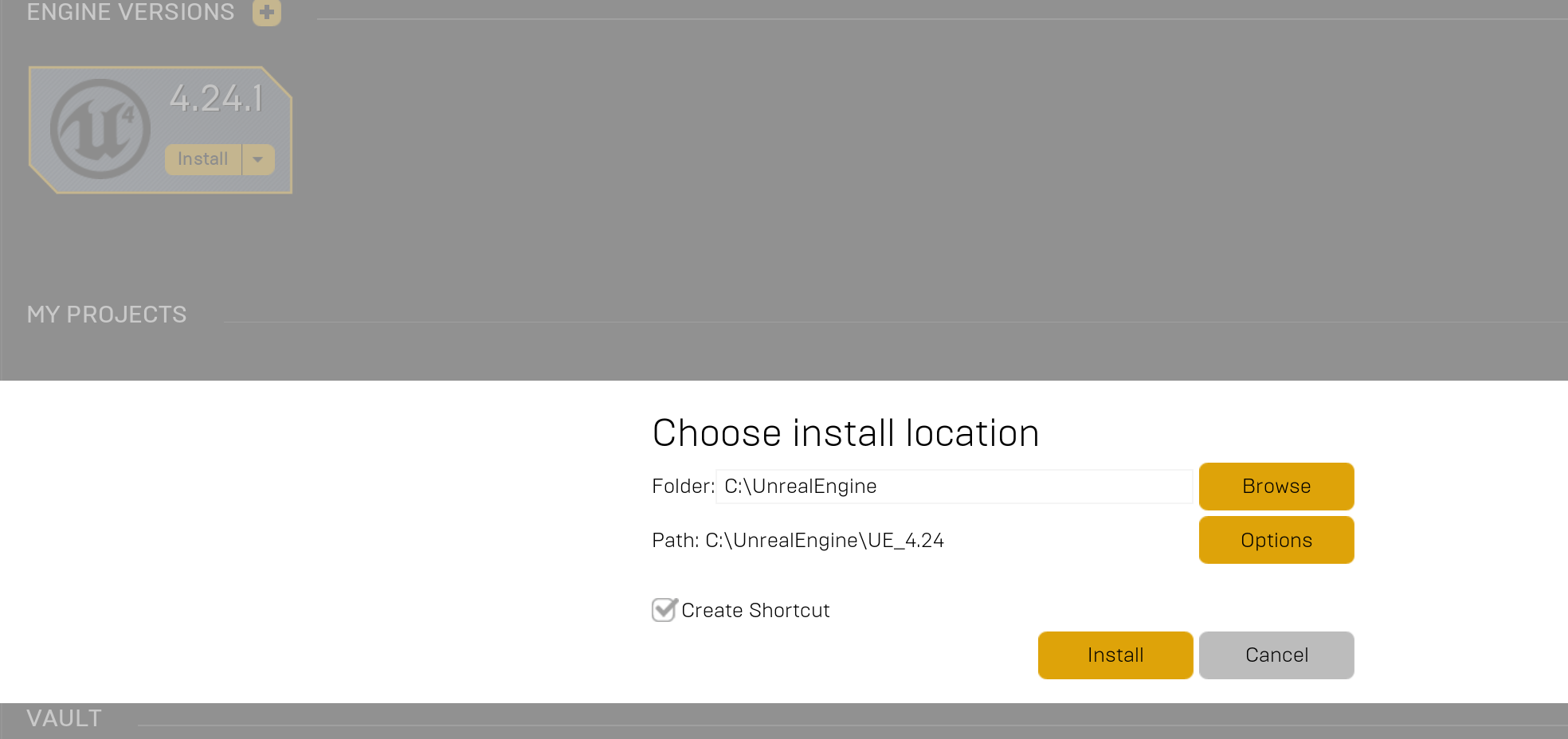
Currently there is not. Geometry Script is being actively developed and the most effective way to see what is coming in the next UE5 Release is to look at what commits have been made in the UE5 Main branch in the Unreal Engine Github. Here is a direct link to the Geometry Script plugin history: https://github.com/EpicGames/UnrealEngine/commits/ue5-main/Engine/Plugins/Experimental/GeometryScripting. Note that this link will not work unless you are logged into GitHub with an account that has access to Unreal Engine, which requires you to sign up for an Epic Games account (more information here).

None of these Geometry Script functions show up for me in the Blueprint Editor

You probably don’t have the Geometry Script plugin enabled. It is not enabled by default. The first video in my Geometry Script Tutorial Playlist on Youtube shows how to turn on the Plugin.

Some functions are missing when I try to use them in my Actor Blueprint

You are likely trying to use a function that is Editor-Only. Some functions like creating new Volumes or StaticMesh/SkeletalMesh Assets, and the Catmull Clark SubD functions, are Editor-Only and can only be used in Editor Utility Actors/Actions/Widgets, or GeneratedDynamicMeshActor BP subclasses.

I can’t find the function “Event On Rebuild Generated Mesh” to override in my Actor Blueprint

This event only exists in Actor Blueprints that derive from the GeneratedDynamicMeshActor class. It’s likely you are trying to find it in a generic Actor Blueprint, or in a DynamicMeshActor Blueprint.

Does Geometry Script always run on the Game Thread?

Currently Yes. Actor Blueprints and Editor Utility Blueprints are always executed on the Game Thread, and so the Geometry Script functions that are called also run on the Game Thread. Some Geometry Script functions will internally execute portions of their work on task threads, eg via C++ calls to ParallelFor, Async, or UE::Tasks::Launch(). However this will only occur in the context of a single function, and the function will not return until all that parallel work is completed.

Can I run GeometryScript functions in a background thread or asynchronously?

It is generally considered to be not safe to modify any UObject in a background thread. Geometry Script functions modify a UDynamicMesh, which is a UObject, and technically it is possible for a UObject to become unreferenced and garbage-collected at any time.

However, if in your specific use case you know that the UObject will not become unreferenced, then most(***) Geometry Script functions can safely be run in a background thread, as long as you don’t try to edit the same mesh from multiple threads. In my article on Modeling Mode Extension Plugins, I demonstrated taking advantage of this to build interactive mesh editing tools using Geometry Script that compute the mesh edit asynchronously.

The (***) above is because any Geometry Script function that touches an Asset, Component, or Actor (eg has any of those as input) cannot safely be run asynchronously.

Is there any built-in support for running Geometry Script functions asynchronously?

No, as of 5.1 there is not.

Can I run a Geometry Script Blueprint on the GPU?

No, this is not possible and won’t ever be. Geometry Script is a thin wrapper around a large C++ library of mesh processing algorithms and data structures. General-purpose C++ code cannot be run directly on a GPU. In addition, many of the mesh processing operations exposed in Geometry Script, like Mesh Booleans, involve complex queries and modifications over unstructured graphs where dynamic memory allocations are generally involved, which is the kind of computation problem that CPUs are much better at than GPUs.

Does Geometry Script work with Skeletal Meshes?

In 5.1 there is limited support for from a SkeletalMesh to a DynamicMesh and back, similar to the StaticMesh approach. However, how to automatically generate or update skin weights after complex mesh edits basically remains an unsolved problem in animation, and so procedural mesh edits done this way likely will not result in desirable skin weights.

Does Geometry Script work with Landscape, Geometry Caches, Geometry Collections, Hair/Grooms, Cloth Meshes, or some other UE Geometry Representation?

Not in UE 5.1. Nearly all Geometry Script functions only work with UDynamicMesh objects. There are functions to convert the internal mesh representations from Static and Skeletal Meshes, and Volume Actors, into a UDynamicMesh, and then functions to convert back. No such functions currently exist for these other geometry types.

Is Geometry Script Deterministic? Are scripts likely to break in the future?

Most functions in Geometry Script are deterministic. Several are not, however - in particular mesh simplification and remeshing functions currently may not produce the same mesh every time. In general, it is difficult to provide hard determinism and compatibility guarantees in procedural mesh generation systems, as things that are clear bugs or performance issues can change the result mesh when they are fixed/resolved. Deterministic versions of operations may also be slower, as in some cases the most efficient parallel-processing implementation produces non-determinism. Operations like a Mesh Boolean can have a huge dependency tree of geometric operations, and any change to one of them might affect the result. So the only way to ensure deterministic compatibility is to keep the “old” version of the code around, bloating the binary size (this is what CAD software generally does to ensure compatibility between versions).

Can I animate a mesh with Geometry Scripting? Can I implement my own skinning or vertex deformation?

This is technically possible, either by fully regenerating the mesh every frame, or by (for example) using Geometry Script to update the vertex positions of a DynamicMesh every frame. However, this is not a very efficient way to implement animation, and except for very simple examples (eg say a simple primitive shapes, basic mesh booleans, etc) is unlikely to provide acceptable runtime performance. Each time the DynamicMesh is regenerated or updated, a series of relatively expensive operations occur, including generating new vertex and index buffers and uploading them to the GPU (this GPU upload is often the most expensive part). Skinning in something like a SkeletalMesh is computed directly on the GPU and so is much, much faster.

However if you don’t need to update the deformation every frame, or don’t need realtime performance (ie for experimental or research purposes), Geometry Scripting may work for you. It is possible to (eg) iterate over all mesh vertices and update their positions, even for meshes with millions of vertices.

Runtime Usage

Can I use Geometry Script in my Game / At Runtime?

Mostly Yes. Some Geometry Script functions are Editor-Only, but the majority work at Runtime. Notable things that do not work at Runtime include creating new Volume actors, creating/updating Static or Skeletal meshes, and Catmull Clark SubD.

Should I use DynamicMeshActors generated with Geometry Script in my Game?

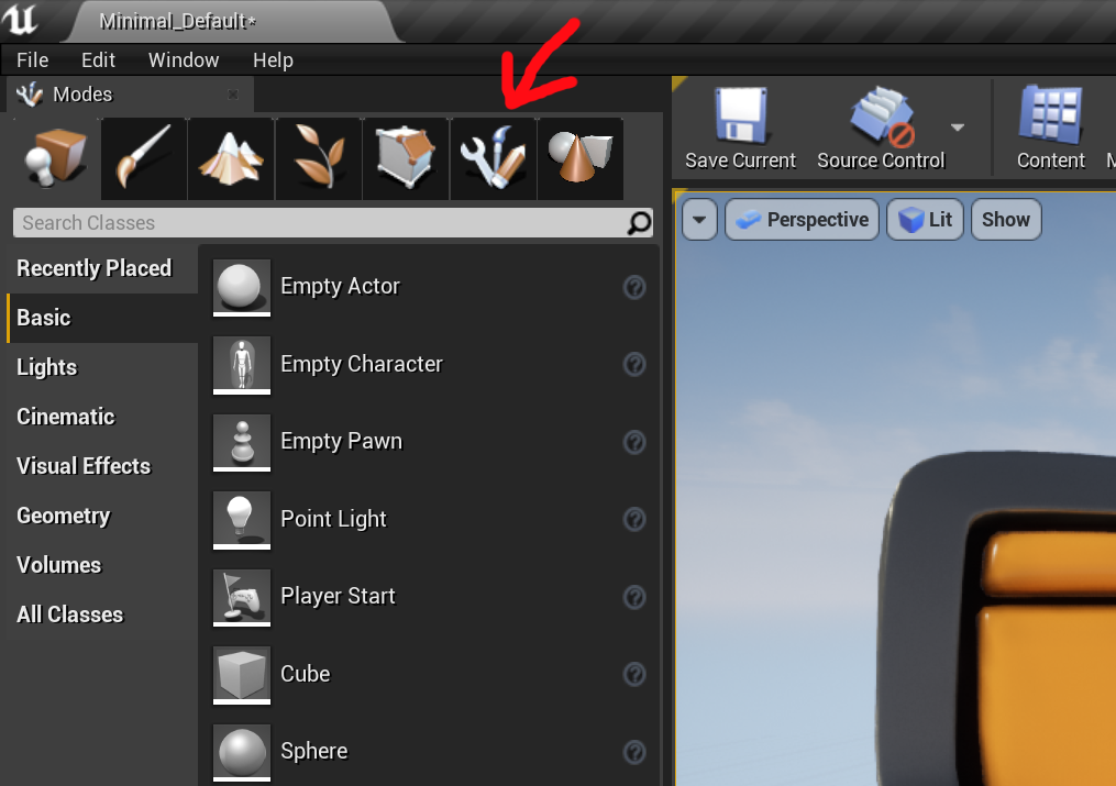
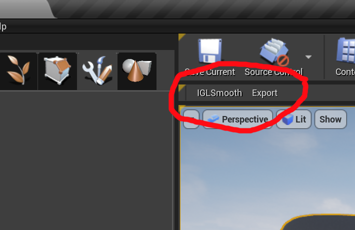
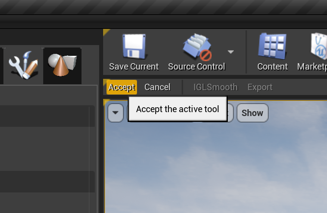
If your meshes are static in the Game, IE you just want the convenience of procedural mesh generation for in-Editor Authoring, then the answer is probably no. DynamicMeshComponent (the component underlying DynamicMeshActor) is relatively expensive compared to StaticMeshComponent (see below). You should almost certainly “bake” any generated DynamicMeshActors into StaticMesh/Component/Actors, that’s what we did in the Lyra sample game. I have a short tutorial video on doing so here.

If your meshes are dynamic, ie they need to be dynamically generated at Runtime, or modified in-Game, then the answer is probably yes. There are various other options like ProceduralMeshComponent, the third-party RuntimeMeshComponent which is quite good, and runtime-generated StaticMesh Assets. However none of these options has an internal UDynamicMesh that can be directly edited with Geometry Script.

Will DynamicMeshComponent be as efficient as StaticMeshComponent in my Game?

No. DynamicMeshComponent uses the Dynamic Draw Path instead of the Static Draw Path, which has more per-frame rendering overhead (there is a GDC talk on YouTube about the Unreal Engine Rendering Pipeline by Marcus Wassmer which explains the Static Draw Path optimizations for Static Meshes). DynamicMeshComponent does not support instanced rendering, so mesh memory usage is generally higher. And the GPU index/vertex buffers created by a DynamicMeshComponent are not as optimized as those in a cooked StaticMesh asset (really, really not as optimized).

In addition, the DynamicMeshComponent always keeps the UDynamicMesh memory available on the CPU - a cooked StaticMesh Asset usually does not. The FDynamicMesh3 class underlying UDynamicMesh also has a minimum size and grows in fixed “chunks” of memory, so (eg) a one-triangle DynamicMesh will consume quite a bit more memory than a comparable one-triangle StaticMesh’s FMeshDescription would.

Why are all my GeneratedDynamicMeshActors disappearing in PIE or my built game ?!?

GeneratedDynamicMeshActor is an Editor-Only subclass of DynamicMeshActor, meant for in-Editor procedural mesh generation. GeneratedDynamicMeshActor’s convenient “rebuild” system is usually not appropriate in a game context, where you likely need to more precisely manage when meshes are generated/etc. I have a short tutorial video here on how to set up a DynamicMeshActor that can be generated/edited at Runtime.

Is GeometryScript function X fast enough to use in my game?

Since Geometry Script works on Meshes, which have a variable number of triangles and vertices, the only answer anyone can ever give to this question is “you will have to try it and profile”. Any non-trivial function in Geometry Script is at least linear in the number of vertices/triangles, and many are more complex. For example the Mesh Boolean node must build an AABBTree for each of the two input meshes, then do relatively expensive pairwise-triangle intersection tests (based on the AABBTree traversal, which efficiently skips most non-intersections). If you have two basic cubes, this is quite fast. If you try to subtract a cube every frame, the mesh will accumulate more and more triangles over time, and the Boolean will become increasingly expensive.

How can I save/load Dynamic Meshes at Runtime?

Unreal Engine doesn’t provide any built-in mesh load/save system at Runtime. You would have to implement this yourself in C++. There is a system called Datasmith Runtime which can load various mesh formats at Runtime but this is not part of Geometry Scripting.

Can I use Geometry Script to modify Static Meshes in my Level at Runtime?

No, this is not possible. Static Mesh Assets you created in the Editor and placed in a level are “cooked” when you create your game executable. It is not possible to update a cooked asset at Runtime, the mesh data has been converted to optimized GPU index and vertex buffers.

The function “Copy Mesh From Static Mesh” is not working at Runtime

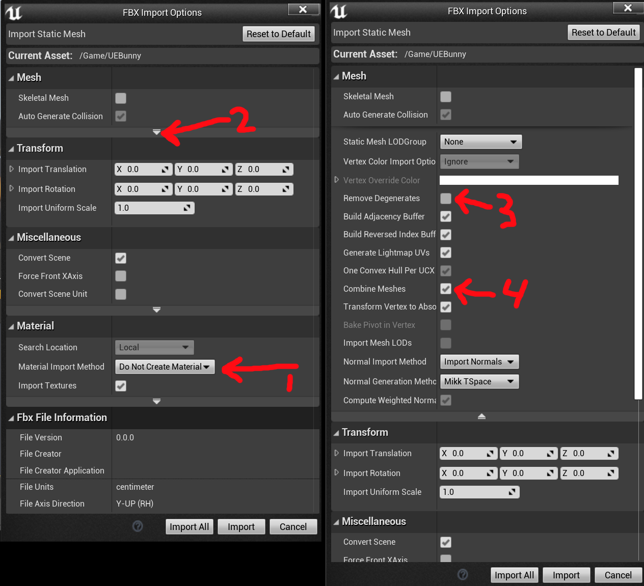
Try checking the Output Log, you will likely see that there are warning messages about the “Allow CPU Access” flag on the Static Mesh Asset. You must enable this flag in the Editor to be able to access the StaticMesh index and vertex buffers on the CPU at Runtime. Note that this will increase memory usage for the Asset.

The Mesh I get when using “Copy Mesh From Static Mesh” at Runtime is different than the mesh I get in the Editor

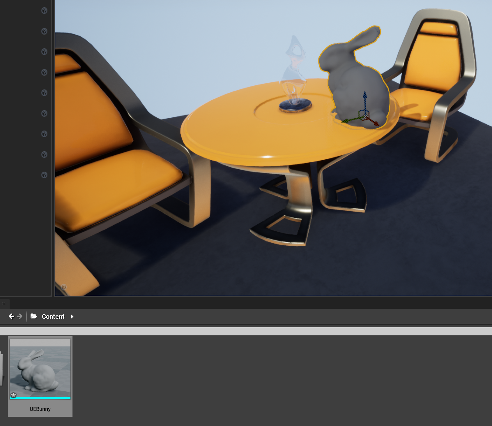
In the Editor, by default CopyMeshFromStaticMesh will access the “Source” mesh, however at Runtime the Source mesh is not available. Even with the Allow CPU Access flag enabled, at Runtime only the “cooked” index and vertex buffers that will be passed to the GPU are available on the CPU. This representation of the mesh does not support “shared” or “split” UVs or normals, the mesh will be split along any UV and hard-normal seams. So what would be a closed solid cube in the Editor will become 6 disconnected rectangles in the index/vertex buffer representation. This is problematic for many mesh modeling operations. You can in many cases use the Weld Mesh Edges function to merge the mesh back together at the added seams, however this may introduce other problems, and very small triangles may have been fully discarded.

The functions “Apply Displace from Texture Map” and/or “Sample Texture2D at UV Positions” are working in the Editor but not at Runtime

Try checking the Output Log, you will likely see warning messages about Texture Compression. In their cooked representation, Texture2D Assets are generally compressed in formats that can only be efficiently decompressed on the GPU, and so are not readable in Geometry Script. The VectorDisplacementMap texture compression mode in the Texture2D Asset is effectively uncompressed RGBA8, so you must configure a Texture asset with this compression mode in the Editor for it to be readable at Runtime.

Rendering and UE Features

Does DynamicMeshComponent support Nanite, Lumen, or Mesh Distance Fields?

As of 5.1, no.

Does DynamicMeshComponent work with Runtime Virtual Texturing (RVT)?

As of 5.1, no. RVT requires usage of the Static Draw Path, and DynamicMeshComponent uses the Dynamic Draw Path

Does DynamicMeshComponent support Physics / Collision?

Yes. DynamicMeshComponent supports both Complex and Simple collision, similar to StaticMesh. The Collision settings and geometry are stored on the DynamicMeshComponent, not the DynamicMesh directly (unlike how they are stored on a StaticMesh Asset). So, to set collision geometry or change settings, you must call functions on the Component, not on the DynamicMesh.

DynamicMeshComponents don’t show up in Collision Debug Views!

This is currently not supported in UE 5.1

Does DynamicMeshComponent support LODs?

No.

Does DynamicMeshComponent support Instanced Rendering?

As of 5.1, no.

Lyra Sample Game

How does the Non-Destructive Level Design with GeometryScript-based mesh generator “Tool” objects work in Lyra?

I wrote extensive documentation for the Lyra Tool system here: https://docs.unrealengine.com/5.0/en-US/lyra-geometry-tools-in-unreal-engine/. The basic principle is that StaticMeshComponents are linked with a GeneratedDynamicMeshActor “Tool” mesh generator which still exists in the level (they are “stored” under the map). A helper Actor called the “Cold Storage” is used to maintain links between the Tool instance and it’s Components. Each Tool must be associated with a single StaticMesh Asset.

How can I migrate the Lyra Tool system to my own project?

This is somewhat complex, and the simplest route would be to migrate your content in a copy of the Lyra game. However several users have figured out how to migrate from Lyra to your own project. This YouTube tutorial by BuildGamesWithJohn is one that I believe will work, and other users have reported that this tutorial by JohnnyTriesVR will also work.

Command-Line Mesh Processing with Unreal Engine 4.26

This is the first of several tutorials that will (hopefully) teach you how to do advanced Mesh/Geometry Processing with Unreal Engine. Past Gradientspace Tutorials focused on the open-source Geometry3Sharp library that I developed in C#, and demonstrated how to do things like Mesh Simplification, Remeshing, Implicit Surface Modeling, and so on. G3Sharp became quite powerful, I used it to create the Cotangent 3D printing tool, and helped others use it to build Archform (a tool for designing dental aligners) and NiaFit (for designing 3D printable prosthetics). Quite a few other developers seemed to like it, too.

However, ultimately C# became a limiting factor for G3Sharp. I really like coding in C#, but the performance cost can be high, and critical math libraries like sparse linear solvers are missing from the C# ecosystem. The thought of porting even more WildMagic/GTEngine code, it was just too much! So, in December 2018 I joined Epic Games and started a C++ port of G3Sharp. Thanks to the hard work of the UE Geometry Team, this library - the GeometryProcessing plugin - has now far surpassed G3Sharp in capability. So, I think it’s about time to start showing you how to use it.

In this tutorial, I am going to walk you through a single example that generates all the meshes in the image below. In doing so, we will cover the main content of most of the previous GradientSpace G3Sharp tutorials, but in C++, in Unreal Engine. To avoid any UE complexity in this intro tutorial, we’re going to do everything in a simple command-line tool. But keep in mind that everything we’re going to do is available both in the Editor, and in-game at Runtime.

(Mandatory Disclaimer: your author, Ryan Schmidt, is an employee of Epic Games)

Translation for Chinese users: https://zhuanlan.zhihu.com/p/343789879

Preliminaries / UE4 Setup

Click to Enlarge

One small hurdle we have to overcome is that binary UE4 engine installations cannot build command-line executables. So, we’ll need to use the UE4 source, which you can get on Github once you have joined the Epic Games Github Organization (click link for instructions - it’s free for anyone who accepts the UE4 license agreement). This tutorial depends on code only available in version 4.26 or later, so I suggest you use the 4.26 branch (https://github.com/EpicGames/UnrealEngine/tree/4.26) directly (this tutorial should also work against the Release branch by the time you read it).

The simplest thing to do (in my opinion) is to use the Download Zip option, available under the Code drop-down button (see image to the right). Download and unzip (this will require about 1.7 GB of disk space). After that, you’ll need to run the Setup.bat file in the top-level folder, which will download another ~11GB of binary files and then run an installer that unpacks that into another ~40 GB. Unfortunately there is no more compact variant. Time for coffee!

The code for this tutorial is available on GitHub in the gradientspace UnrealMeshProcessingTools repository (click for link), in a folder named CommandLineGeometryTest in the UE4.26 samples subfolder. Again, you can download a zip of the top-level repository (click for direct link), or you can sync with a git client, too.

Assuming you unzipped the UE repository into a folder named “UnrealEngine-4.26”, then you’ll need to copy or move the sample code folder UE4.26\CommandLineGeometryTest to the path UnrealEngine-4.26\Engine\Source\Programs\, as shown in the image on the right. This folder contains various other command-line tools and apps that UE uses. You might be able to put it in other places, but this is where I tested it from, and where the sample HoleyBunny.obj file paths are hardcoded relative to.

For reference, I created this sample project based on the BlankProgram command-line executable that is included with the Engine (you can see it in the list on the right). This is a minimal Hello-World example program and a good starting point for any command-line executable based on UE (eg for unit testing, etc). The only modification I had to make to get things to work was to add references to several of the modules in the GeometryProcessing plugin, in the CommandLineGeometryTest.Build.cs file:

PrivateDependencyModuleNames.Add("GeometricObjects");
PrivateDependencyModuleNames.Add("DynamicMesh");

If you wanted to use these modules in other projects, you will have to do the same. Note that many parts of the Engine are not immediately available in a command-line or “Program” target type. For example in BlankProgram the UObject system is not initialized. The GeometryProcessing plugin modules have minimal engine dependencies, and do not define UObjects, so this is not a problem for this tutorial. (It is possible to initialize various engine systems, see for example the SlateViewer program.)

click to enlarge

Once you have the files in the right place, run the top-level GenerateProjectFiles.bat file. This will generate a Visual Studio 2019 UE4.sln file. Oh, by the way, you probably want to have Visual Studio 2019 installed, if you are on Windows. If you are on Linux or OSX, there are .command/.sh versions of the batch files I mentioned above, and this tutorial should work on those platforms, too. (GeometryProcessing has already been used in shipping games on desktop, mobile, and console platforms!!)

Open up UE4.sln, and you will find a long list of projects in the Solution Explorer subwindow. Find our CommandLineGeometryTest project, right-click on it, and select the Set as Startup Project option that appears in the context menu. Then click the Start Debugging button or hit F5. This will build for a minute or so, then pop up a command-line dialog box and print a bit of info as the tutorial runs (should only be a few seconds, though).

Note that this is not a full build of UE4. Since we are building a simple command-line app, we don’t have any dependencies on the majority of the Engine, or the Editor. A full build would take much longer - from ~15 minutes on my 24-core Threadripper to well over 2 hours on my 4-core laptop. So, make sure you don’t do a “Build Solution” or “Rebuild All”, or you are in for a long wait.

Tutorial Files

The sample code contains just a few files, all the code we care about is in CommandLineGeometryTest.cpp. The CommandLineGeometryTest.Build.cs and CommandLineGeometryTest.Target.cs are configuration files for the CommandLineGeometryTest UE4 module, and the CommandLineGeometryTest.h is empty.

The GeometryProcessing module does not natively support any file I/O, so the DynamicMeshOBJReader.h and DynamicMeshOBJWriter.h are necessary to read/write OBJ mesh files. The OBJ Reader is just a wrapper around the tinyobjloader library (https://github.com/tinyobjloader/tinyobjloader, source is embedded) which constructs a FDynamicMesh3 (the mesh class we will use). The OBJ Writer is minimalist, but does the basics.

CommandLineGeometryTest.cpp just contains #includes and a main() function, and I'm going to paste the entire tutorial code below. We'll step through the blocks afterwards, but I think it's instructive to skim through it all first. In less than 150 lines, this code demonstrates normals calculation, sphere and box generators, Mesh AABBTree setup and queries (nearest-point and ray-intersection), appending meshes, fast-winding-number-based resampling, implicit morphological operations, mesh simplification, isotropic remeshing, mesh hole filling, and mesh booleans (twice) ((yes, MESH BOOLEANS zomg!!)) :

// import an OBJ mesh. The path below is relative to the default path that Visual Studio will execute CommandLineGeometryTest.exe,
// when using a normal UE4.26 auto-generated UE.sln file. If things change you might need to update this path
FDynamicMesh3 ImportMesh;
FDynamicMeshOBJReader::Read("..\\..\\Source\\Programs\\CommandLineGeometryTest\\HoleyBunny.obj", ImportMesh, true, true, true);
// flip to UE orientation
ImportMesh.ReverseOrientation();

// print some mesh stats
UE_LOG(LogBlankProgram, Display, TEXT("Mesh has %d vertices, %d triangles, %d edges"), ImportMesh.VertexCount(), ImportMesh.TriangleCount(), ImportMesh.EdgeCount());
UE_LOG(LogBlankProgram, Display, TEXT("Mesh has %d normals"), ImportMesh.Attributes()->PrimaryNormals()->ElementCount());
UE_LOG(LogBlankProgram, Display, TEXT("Mesh has %d UVs"), ImportMesh.Attributes()->PrimaryUV()->ElementCount());

// compute per-vertex normals
FMeshNormals::QuickComputeVertexNormals(ImportMesh);

// generate a small box mesh to append multiple times
FAxisAlignedBox3d ImportBounds = ImportMesh.GetBounds();
double ImportRadius = ImportBounds.DiagonalLength() * 0.5;
FMinimalBoxMeshGenerator SmallBoxGen;
SmallBoxGen.Box = FOrientedBox3d(FVector3d::Zero(), ImportRadius * 0.05 * FVector3d::One());
FDynamicMesh3 SmallBoxMesh(&SmallBoxGen.Generate());

// create a bounding-box tree, then copy the imported mesh and make an Editor for it
FDynamicMeshAABBTree3 ImportBVTree(&ImportMesh);
FDynamicMesh3 AccumMesh(ImportMesh);
FDynamicMeshEditor MeshEditor(&AccumMesh);

// append the small box mesh a bunch of times, at random-ish locations, based on a Spherical Fibonacci distribution
TSphericalFibonacci<double> PointGen(64);
for (int32 k = 0; k < PointGen.Num(); ++k)
{
    // point on a bounding sphere
    FVector3d Point = (ImportRadius * PointGen.Point(k)) + ImportBounds.Center();

    // compute the nearest point on the imported mesh
    double NearDistSqr;
    int32 NearestTriID = ImportBVTree.FindNearestTriangle(Point, NearDistSqr);
    if (ImportMesh.IsTriangle(NearestTriID) == false)
        continue;
    FDistPoint3Triangle3d DistQueryResult = TMeshQueries<FDynamicMesh3>::TriangleDistance(ImportMesh, NearestTriID, Point);

    // compute the intersection between the imported mesh and a ray from the point to the mesh center
    FRay3d RayToCenter(Point, (ImportBounds.Center() - Point).Normalized() );
    int32 HitTriID = ImportBVTree.FindNearestHitTriangle(RayToCenter);
    if (HitTriID == FDynamicMesh3::InvalidID)
        continue;
    FIntrRay3Triangle3d HitQueryResult = TMeshQueries<FDynamicMesh3>::TriangleIntersection(ImportMesh, HitTriID, RayToCenter);

    // pick the closer point
    bool bUseRayIntersection = (HitQueryResult.RayParameter < DistQueryResult.Get());
    FVector3d UsePoint = (bUseRayIntersection) ? RayToCenter.PointAt(HitQueryResult.RayParameter) : DistQueryResult.ClosestTrianglePoint;

    FVector3d TriBaryCoords = (bUseRayIntersection) ? HitQueryResult.TriangleBaryCoords : DistQueryResult.TriangleBaryCoords;
    FVector3d UseNormal = ImportMesh.GetTriBaryNormal(NearestTriID, TriBaryCoords.X, TriBaryCoords.Y, TriBaryCoords.Z);

    // position/orientation to use to append the box
    FFrame3d TriFrame(UsePoint, UseNormal);

    // append the box via the Editor
    FMeshIndexMappings TmpMappings;
    MeshEditor.AppendMesh(&SmallBoxMesh, TmpMappings,
        [TriFrame](int32 vid, const FVector3d& Vertex) { return TriFrame.FromFramePoint(Vertex); },
        [TriFrame](int32 vid, const FVector3d& Normal) { return TriFrame.FromFrameVector(Normal); });
}

// make a new AABBTree for the accumulated mesh-with-boxes
FDynamicMeshAABBTree3 AccumMeshBVTree(&AccumMesh);
// build a fast-winding-number evaluation data structure
TFastWindingTree<FDynamicMesh3> FastWinding(&AccumMeshBVTree);

// "solidify" the mesh by extracting an iso-surface of the fast-winding field, using marching cubes
// (this all happens inside TImplicitSolidify)
int32 TargetVoxelCount = 64;
double ExtendBounds = 2.0;
TImplicitSolidify<FDynamicMesh3> SolidifyCalc(&AccumMesh, &AccumMeshBVTree, &FastWinding);
SolidifyCalc.SetCellSizeAndExtendBounds(AccumMeshBVTree.GetBoundingBox(), ExtendBounds, TargetVoxelCount);
SolidifyCalc.WindingThreshold = 0.5;
SolidifyCalc.SurfaceSearchSteps = 5;
SolidifyCalc.bSolidAtBoundaries = true;
SolidifyCalc.ExtendBounds = ExtendBounds;
FDynamicMesh3 SolidMesh(&SolidifyCalc.Generate());
// position the mesh to the right of the imported mesh
MeshTransforms::Translate(SolidMesh, SolidMesh.GetBounds().Width() * FVector3d::UnitX());

// offset the solidified mesh
double OffsetDistance = ImportRadius * 0.1;
TImplicitMorphology<FDynamicMesh3> ImplicitMorphology;
ImplicitMorphology.MorphologyOp = TImplicitMorphology<FDynamicMesh3>::EMorphologyOp::Dilate;
ImplicitMorphology.Source = &SolidMesh;
FDynamicMeshAABBTree3 SolidSpatial(&SolidMesh);
ImplicitMorphology.SourceSpatial = &SolidSpatial;
ImplicitMorphology.SetCellSizesAndDistance(SolidMesh.GetCachedBounds(), OffsetDistance, 64, 64);
FDynamicMesh3 OffsetSolidMesh(&ImplicitMorphology.Generate());

// simplify the offset mesh
FDynamicMesh3 SimplifiedSolidMesh(OffsetSolidMesh);
FQEMSimplification Simplifier(&SimplifiedSolidMesh);
Simplifier.SimplifyToTriangleCount(5000);
// position to the right
MeshTransforms::Translate(SimplifiedSolidMesh, SimplifiedSolidMesh.GetBounds().Width() * FVector3d::UnitX());

// generate a sphere mesh
FSphereGenerator SphereGen;
SphereGen.Radius = ImportMesh.GetBounds().MaxDim() * 0.6;
SphereGen.NumPhi = SphereGen.NumTheta = 10;
SphereGen.bPolygroupPerQuad = true;
SphereGen.Generate();
FDynamicMesh3 SphereMesh(&SphereGen);

// generate a box mesh
FGridBoxMeshGenerator BoxGen;
BoxGen.Box = FOrientedBox3d(FVector3d::Zero(), SphereGen.Radius * FVector3d::One());
BoxGen.EdgeVertices = FIndex3i(4, 5, 6);
BoxGen.bPolygroupPerQuad = false;
BoxGen.Generate();
FDynamicMesh3 BoxMesh(&BoxGen);

// subtract the box from the sphere (the box is transformed within the FMeshBoolean)
FDynamicMesh3 BooleanResult;
FMeshBoolean DifferenceOp(
    &SphereMesh, FTransform3d::Identity(),
    &BoxMesh, FTransform3d(FQuaterniond(FVector3d::UnitY(), 45.0, true), SphereGen.Radius*FVector3d(1,-1,1)),
    &BooleanResult, FMeshBoolean::EBooleanOp::Difference);
if (DifferenceOp.Compute() == false)
{
    UE_LOG(LogBlankProgram, Display, TEXT("Boolean Failed!"));
}
FAxisAlignedBox3d BooleanBBox = BooleanResult.GetBounds();
MeshTransforms::Translate(BooleanResult, 
    (SimplifiedSolidMesh.GetBounds().Max.X + 0.6*BooleanBBox.Width())* FVector3d::UnitX() + 0.5*BooleanBBox.Height()*FVector3d::UnitZ());

// make a copy of the boolean mesh, and apply Remeshing
FDynamicMesh3 RemeshBoolMesh(BooleanResult);
RemeshBoolMesh.DiscardAttributes();
FQueueRemesher Remesher(&RemeshBoolMesh);
Remesher.SetTargetEdgeLength(ImportRadius * 0.05);
Remesher.SmoothSpeedT = 0.5;
Remesher.FastestRemesh();
MeshTransforms::Translate(RemeshBoolMesh, 1.1*RemeshBoolMesh.GetBounds().Width() * FVector3d::UnitX());

// subtract the remeshed sphere from the offset-solidified-cubesbunny
FDynamicMesh3 FinalBooleanResult;
FMeshBoolean FinalDifferenceOp(
    &SimplifiedSolidMesh, FTransform3d(-SimplifiedSolidMesh.GetBounds().Center()),
    &RemeshBoolMesh, FTransform3d( (-RemeshBoolMesh.GetBounds().Center()) + 0.5*ImportRadius*FVector3d(0.0,0,0) ),
    &FinalBooleanResult, FMeshBoolean::EBooleanOp::Intersect);
FinalDifferenceOp.Compute();

// The boolean probably has some small cracks around the border, find them and fill them
FMeshBoundaryLoops LoopsCalc(&FinalBooleanResult);
UE_LOG(LogBlankProgram, Display, TEXT("Final Boolean Mesh has %d holes"), LoopsCalc.GetLoopCount());
for (const FEdgeLoop& Loop : LoopsCalc.Loops)
{
    FMinimalHoleFiller Filler(&FinalBooleanResult, Loop);
    Filler.Fill();
}
FAxisAlignedBox3d FinalBooleanBBox = FinalBooleanResult.GetBounds();
MeshTransforms::Translate(FinalBooleanResult,
    (RemeshBoolMesh.GetBounds().Max.X + 0.6*FinalBooleanBBox.Width())*FVector3d::UnitX() + 0.5*FinalBooleanBBox.Height()*FVector3d::UnitZ() );

// write out the sequence of meshes
    FDynamicMeshOBJWriter::Write("..\\..\\Source\\Programs\\CommandLineGeometryTest\\HoleyBunny_processed.obj", 
    { AccumMesh, SolidMesh, SimplifiedSolidMesh, BooleanResult, RemeshBoolMesh, FinalBooleanResult }, true);


Import and Attributes

Ok lets step through the code. The first block just reads a mesh, prints some information, and computes normals (just a reminder, as I mentioned above, FDynamicMeshOBJReader is not part of UE4, this is a class included with the sample code). Note the call to FDynamicMesh3::ReverseOrientation(). Whether this is necessary depends on your input file, but generally, UE4 uses a left-handed coordinate system, while most content tools are right-handed. This means that a right-handed mesh, when imported into UE4, will be “inside-out”, and so (for example) the positive/outward surface normal direction for that mesh would point inwards. If we ReverseOrientation() on import, and again on export, then things will be fine.

// import an OBJ mesh. The path below is relative to the default path that Visual Studio will execute CommandLineGeometryTest.exe,
// when using a normal UE4.26 auto-generated UE.sln file. If things change you might need to update this path
FDynamicMesh3 ImportMesh;
FDynamicMeshOBJReader::Read("..\\..\\Source\\Programs\\CommandLineGeometryTest\\HoleyBunny.obj", ImportMesh, true, true, true);
// flip to UE orientation
ImportMesh.ReverseOrientation();

// print some mesh stats
UE_LOG(LogBlankProgram, Display, TEXT("Mesh has %d vertices, %d triangles, %d edges"), ImportMesh.VertexCount(), ImportMesh.TriangleCount(), ImportMesh.EdgeCount());
UE_LOG(LogBlankProgram, Display, TEXT("Mesh has %d normals"), ImportMesh.Attributes()->PrimaryNormals()->ElementCount());
UE_LOG(LogBlankProgram, Display, TEXT("Mesh has %d UVs"), ImportMesh.Attributes()->PrimaryUV()->ElementCount());

// compute per-vertex normals
FMeshNormals::QuickComputeVertexNormals(ImportMesh);

There is nothing special about the logging calls, I just wanted to have a reason to mention the calls to Attributes(), which return a FDynamicMeshAttributeSet. The design of FDynamicMesh3 is quite similar to DMesh3 from Geometry3Sharp, to the point where this documentation on DMesh3 basically applies directly to FDynamicMesh3. However, one major addition that has been made in the GeometryProcesing implementation is support for arbitrary Attribute Sets, including per-triangle indexed Attributes which allow for representation of things like split normals and proper UV islands/atlases/overlays (depending on your preferred terminology). Generally, mesh editing operations in GeometryProcessing (eg like the mesh edge splits/flips/collapses, the FDynamicMeshEditor, the Simplifier and Remeshers, change tracking, etc) handle updating the Attribute Sets automatically.

Generating a Box Mesh

The next step is to generate a simple box, that we are going to append to the imported bunny a bunch of times. There are a variety of mesh generators in the /Public/Generators/ subfolder in the GeometricObjects module. FMinimalBoxMeshGenerator makes a box with 12 triangles, and we’ll use FGridBoxMeshGenerator later to generate a subdivided box. The GeometricObjects module also includes a library of basic geometry and vector-math types, templated on Real type, with typedefs for float and double. So FAxisAlignedBox3d is a 3D double-precision axis-aligned bounding box, while FAxisAlignedBox2f is a 2D float variant. Conversions to the standard FVector/FBox/etc UE4 types are defined wherever possible (implicit where safe, otherwise via casts). However generally the GeometryProcessing library will calculate in double precision if not templated on Real type.

// generate a small box mesh to append multiple times
FAxisAlignedBox3d ImportBounds = ImportMesh.GetBounds();
double ImportRadius = ImportBounds.DiagonalLength() * 0.5;
FMinimalBoxMeshGenerator SmallBoxGen;
SmallBoxGen.Box = FOrientedBox3d(FVector3d::Zero(), ImportRadius * 0.05 * FVector3d::One());
FDynamicMesh3 SmallBoxMesh(&SmallBoxGen.Generate());

You will note that nearly every type is prefixed with “F”. This is a UE4 convention, generally all structs and classes have an F prefix. Similarly the code here basically follows the UE4 coding standard (which includes quite a bit more whitespace than I generally prefer, but it is what it is).

Making an AABBTree

This is a one-liner, the constructor for FDynamicMeshAABBTree3 will automatically build the AABBTree (this can be disabled with an optional argument). The AABBTree construction is quite fast and there generally is no excuse to use something less reliable (or, horror of horrors, a linear search). Similarly copying a FDynamicMesh3 is very quick, as the storage for the mesh does not involve per-element pointers, it is all in chunked arrays (see TDynamicVector) that can be memcopied. Finally this block creates a FDynamicMeshEditor, which implements a many common low-level mesh editing operations. If you need to do something it doesn’t do, it’s generally a better idea to try and break your problem down into operations that are already implemented, even at the cost of some efficiency, as handling Attribute Set updates gets quite hairy.

// create a bounding-box tree, then copy the imported mesh and make an Editor for it
FDynamicMeshAABBTree3 ImportBVTree(&ImportMesh);
FDynamicMesh3 AccumMesh(ImportMesh);
FDynamicMeshEditor MeshEditor(&AccumMesh);

If you were to look at the code for FDynamicMeshAABBTree3, you would find that it is just a typedef for TMeshAABBTree3<FDynamicMesh3>. The AABBTree is templated on mesh type, as only a few functions on the mesh are required. The FTriangleMeshAdapterd struct can be used to wrap virtually any indexed mesh in an API that will work with TMeshAABBTree3, as well as TMeshQueries<T> which supports many types of generic mesh…queries.

AABBTree Queries

This is a large block because we’re going to do a bit of logic, but the critical parts are the calls to FDynamicMeshAABBTree3::FindNearestTriangle() and FDynamicMeshAABBTree3::FindNearestHitTriangle(). These are two of the most common queries on an AABBTree. Note that in both cases, the query only returns an integer triangle ID/index, and then TMeshQueries<T> is used to execute and return a FDistPoint3Triangle3d/FIntrRay3Triangle3d object. Those classes can also be used directly. They return various information calculated for a point-triangle distance query, or ray-tri intersection. Distance and Intersection queries in GeometryProcessing are generally implemented in this style, and the calculation objects store any useful intermediate information which otherwise might be discarded. In some cases the FDistXY / FIntrXY class has static functions that will do a more minimal computation. The AABBTree class also has a ::FindNearestPoint() helper function (but no similar ray-intersection variant).

// append the small box mesh a bunch of times, at random-ish locations, based on a Spherical Fibonacci distribution
TSphericalFibonacci<double> PointGen(64);
for (int32 k = 0; k < PointGen.Num(); ++k)
{
    // point on a bounding sphere
    FVector3d Point = (ImportRadius * PointGen.Point(k)) + ImportBounds.Center();

    // compute the nearest point on the imported mesh
    double NearDistSqr;
    int32 NearestTriID = ImportBVTree.FindNearestTriangle(Point, NearDistSqr);
    if (ImportMesh.IsTriangle(NearestTriID) == false)
        continue;
    FDistPoint3Triangle3d DistQueryResult = TMeshQueries<FDynamicMesh3>::TriangleDistance(ImportMesh, NearestTriID, Point);

    // compute the intersection between the imported mesh and a ray from the point to the mesh center
    FRay3d RayToCenter(Point, (ImportBounds.Center() - Point).Normalized() );
    int32 HitTriID = ImportBVTree.FindNearestHitTriangle(RayToCenter);
    if (HitTriID == FDynamicMesh3::InvalidID)
        continue;
    FIntrRay3Triangle3d HitQueryResult = TMeshQueries<FDynamicMesh3>::TriangleIntersection(ImportMesh, HitTriID, RayToCenter);

    // pick the closer point
    bool bUseRayIntersection = (HitQueryResult.RayParameter < DistQueryResult.Get());
    FVector3d UsePoint = (bUseRayIntersection) ? RayToCenter.PointAt(HitQueryResult.RayParameter) : DistQueryResult.ClosestTrianglePoint;

    FVector3d TriBaryCoords = (bUseRayIntersection) ? HitQueryResult.TriangleBaryCoords : DistQueryResult.TriangleBaryCoords;
    FVector3d UseNormal = ImportMesh.GetTriBaryNormal(NearestTriID, TriBaryCoords.X, TriBaryCoords.Y, TriBaryCoords.Z);

    // position/orientation to use to append the box
    FFrame3d TriFrame(UsePoint, UseNormal);

    // append the box via the Editor
    FMeshIndexMappings TmpMappings;
    MeshEditor.AppendMesh(&SmallBoxMesh, TmpMappings,
        [TriFrame](int32 vid, const FVector3d& Vertex) { return TriFrame.FromFramePoint(Vertex); },
        [TriFrame](int32 vid, const FVector3d& Normal) { return TriFrame.FromFrameVector(Normal); });
}

The final call in the block above appends the SmallBoxMesh we created above, via the FDynamicMeshEditor. The two lambdas transform the vertices and normals of the box mesh (which is centered at the origin) to be aligned with the surface position and normal we calculated using the distance/ray-intersection. This is done via a FFrame3d, which is a class that is heavily used in GeometryProcessing.

A TFrame3<T> is a 3D position (referred to as the .Origin) and orientation (.Rotation), which is represented as a TQuaternion<T>, so essentially like a standard FTransform without any scaling. However the TFrame3 class has an API that allows you to treat the Frame as a set of 3D orthogonal axes positioned in space. So for example the X(), Y(), and Z() functions return the three axes. There are also various ToFrame() and FromFrame() functions (in the case of FVector3<T> you must differentiate between Point and Vector, but for other types there are overloads). ToFrame() maps geometry into the local coordinate system of the frame, so for example ToFramePoint(P) returns returns a new position that measures the distance from P to the Frame.Origin along each of it’s three axes. FromFrame() does the inverse, mapping points “in” the Frame into “world space” (as far as the Frame is concerned). So in the code above, we are treating the cube as being “in” the Frame coordinate system, and mapping it onto the mesh surface.

A final note, the FFrame3d(Point, Normal) constructor used above results in a Frame with “Z” aligned with the Normal, and somewhat arbitrary X and Y axes. In many cases you might wish to construct a Frame with specific tangent-plane axes. There is a constructor that takes X/Y/Z, but a frequent case is where you have a Normal and another direction that is not necessarily orthogonal to the Normal. In that case you can construct with Z=Normal and then use the ::ConstrainedAlignAxis() function to best-align one of the other Frame axes (eg axis X/0) with a target direction, by rotating around the Z.

“Solidification” with the Fast Mesh Winding Number

Several previous Gradientspace tutorials [1] [2] used the Fast Mesh Winding Number to reliably compute Point Containment (ie inside/outside testing) on meshes. An implementation of the Fast Mesh Winding Number is available in GeometricObjects as TFastWindingTree<T>, where T is FDynamicMesh3 or a MeshAdapter. This data structure is built on top of a TMeshAABBTree<T>. In the code below we construct one of these, and then use a TImplicitSolidify<T> object to generate a new “solidified” mesh. TImplicitSolidify interprets the inside/outside values produced by TFastWindingTree as an Implicit Surface (see previous tutorial) and uses the FMarchingCubes class to generate a triangle mesh for that implicit.

// make a new AABBTree for the accumulated mesh-with-boxes
FDynamicMeshAABBTree3 AccumMeshBVTree(&AccumMesh);
// build a fast-winding-number evaluation data structure
TFastWindingTree<FDynamicMesh3> FastWinding(&AccumMeshBVTree);

// "solidify" the mesh by extracting an iso-surface of the fast-winding field, using marching cubes
// (this all happens inside TImplicitSolidify)
int32 TargetVoxelCount = 64;
double ExtendBounds = 2.0;
TImplicitSolidify<FDynamicMesh3> SolidifyCalc(&AccumMesh, &AccumMeshBVTree, &FastWinding);
SolidifyCalc.SetCellSizeAndExtendBounds(AccumMeshBVTree.GetBoundingBox(), ExtendBounds, TargetVoxelCount);
SolidifyCalc.WindingThreshold = 0.5;
SolidifyCalc.SurfaceSearchSteps = 5;
SolidifyCalc.bSolidAtBoundaries = true;
SolidifyCalc.ExtendBounds = ExtendBounds;
FDynamicMesh3 SolidMesh(&SolidifyCalc.Generate());
// position the mesh to the right of the imported mesh
MeshTransforms::Translate(SolidMesh, SolidMesh.GetBounds().Width() * FVector3d::UnitX());

The TImplicitSolidify code is relatively straightforward, and we could have easily used FMarchingCubes here directly. However, you will find that there are many such “helper” classes like TImplicitSolidify in the GeometryProcessing modules. These classes reduce the amount of boilerplate necessary to do common mesh processing operations, making it easier to implement “recipes” and/or user interfaces that expose certain parameters.

Mesh Morphological Operations and Mesh Simplification

We’ve now generated a “solid” mesh of our holey-bunny-plus-boxes. The next step is to offset this mesh. Offset can be done directly on the mesh triangles, but it can also be considered a Morphological Operation, sometimes referred to as ‘Dilation’ (and a negative offset would be an ‘Erosion’). There are also more interesting Morphological Operations like ‘Opening’ (Erode, then Dilate) and ‘Closure’ (Dilate, then Erode), which is particularly useful for filling small holes and cavities. These are generally quite difficult to implement directly on a mesh, but easily done with implicit surface / level-set techniques in the TImplicitMorphology<T> class. Similar to TImplicitSolidify, this class builds the necessary data structures and uses FMarchingCubes to generate an output mesh.

// offset the solidified mesh
double OffsetDistance = ImportRadius * 0.1;
TImplicitMorphology<FDynamicMesh3> ImplicitMorphology;
ImplicitMorphology.MorphologyOp = TImplicitMorphology<FDynamicMesh3>::EMorphologyOp::Dilate;
ImplicitMorphology.Source = &SolidMesh;
FDynamicMeshAABBTree3 SolidSpatial(&SolidMesh);
ImplicitMorphology.SourceSpatial = &SolidSpatial;
ImplicitMorphology.SetCellSizesAndDistance(SolidMesh.GetCachedBounds(), OffsetDistance, 64, 64);
FDynamicMesh3 OffsetSolidMesh(&ImplicitMorphology.Generate());

// simplify the offset mesh
FDynamicMesh3 SimplifiedSolidMesh(OffsetSolidMesh);
FQEMSimplification Simplifier(&SimplifiedSolidMesh);
Simplifier.SimplifyToTriangleCount(5000);
// position to the right
MeshTransforms::Translate(SimplifiedSolidMesh, SimplifiedSolidMesh.GetBounds().Width() * FVector3d::UnitX());

Marching Cubes meshes are generally very dense, and so it’s a common pattern to Simplify the mesh afterwards. This can be done in a few lines using the FQEMSimplification class, which has a variety of simplification criteria you can specify. There are also several other Simplifier implementations, in particular FAttrMeshSimplification will consider the normal and UV Attribute Overlays.

Mesh Booleans (!!!)

It’s the moment you’ve been waiting for - Mesh Booleans! In this block we first use FSphereGenerator and FGridBoxGenerator to generate two meshes, and then use FMeshBoolean to subtract the Box from the Sphere. The FMeshBoolean constructor takes a transform for each input mesh, but only supports two input meshes (ie it’s not an N-way Boolean). If you would like to use multiple input meshes, you will have to use repeated FMeshBoolean operations, but if the inputs are not intersecting it can be more efficient to combine them using FDynamicMeshEditor::AppendMesh() first.

// generate a sphere mesh
FSphereGenerator SphereGen;
SphereGen.Radius = ImportMesh.GetBounds().MaxDim() * 0.6;
SphereGen.NumPhi = SphereGen.NumTheta = 10;
SphereGen.bPolygroupPerQuad = true;
SphereGen.Generate();
FDynamicMesh3 SphereMesh(&SphereGen);

// generate a box mesh
FGridBoxMeshGenerator BoxGen;
BoxGen.Box = FOrientedBox3d(FVector3d::Zero(), SphereGen.Radius * FVector3d::One());
BoxGen.EdgeVertices = FIndex3i(4, 5, 6);
BoxGen.bPolygroupPerQuad = false;
BoxGen.Generate();
FDynamicMesh3 BoxMesh(&BoxGen);

// subtract the box from the sphere (the box is transformed within the FMeshBoolean)
FDynamicMesh3 BooleanResult;
FMeshBoolean DifferenceOp(
    &SphereMesh, FTransform3d::Identity(),
    &BoxMesh, FTransform3d(FQuaterniond(FVector3d::UnitY(), 45.0, true), SphereGen.Radius*FVector3d(1,-1,1)),
    &BooleanResult, FMeshBoolean::EBooleanOp::Difference);
if (DifferenceOp.Compute() == false)
{
    UE_LOG(LogGeometryTest, Display, TEXT("Boolean Failed!"));
}
FAxisAlignedBox3d BooleanBBox = BooleanResult.GetBounds();
MeshTransforms::Translate(BooleanResult, 
    (SimplifiedSolidMesh.GetBounds().Max.X + 0.6*BooleanBBox.Width())* FVector3d::UnitX() + 0.5*BooleanBBox.Height()*FVector3d::UnitZ());

Note that the MeshBoolean is not 100% reliable. Below I will show how to (try to) handle failures.

Remeshing

Next we apply a pass of isotropic triangular remeshing to the Boolean result. This is a standard step if you are planning on doing further mesh processing like deformations/smoothing/etc, as output of a Mesh Boolean often has highly variable triangle size/density (which constraints how the mesh can move) and sliver triangles that can cause numerical issues. The standard approach is to use FRemesher and run a fixed number of passes over the full mesh. Below I used FQueueRemesher, which produces nearly the same result, but rather than full-mesh passes, an “active queue” of meshes that need to be processed is tracked. This can be significantly faster (particularly on large meshes).

// make a copy of the boolean mesh, and apply Remeshing
FDynamicMesh3 RemeshBoolMesh(BooleanResult);
RemeshBoolMesh.DiscardAttributes();
FQueueRemesher Remesher(&RemeshBoolMesh);
Remesher.SetTargetEdgeLength(ImportRadius * 0.05);
Remesher.SmoothSpeedT = 0.5;
Remesher.FastestRemesh();
MeshTransforms::Translate(RemeshBoolMesh, 1.1*RemeshBoolMesh.GetBounds().Width() * FVector3d::UnitX());

I covered the basics of Isotropic Remeshing in a previous G3Sharp tutorial. That tutorial basically applies directly to the UE4 GeometryProcessing implementation, down to the type and field names (don’t forget to add F). However the UE4 version is quite a bit more capable, for example the FQueueRemesher is much faster, and there is also FSubRegionRemesher which can remesh a portion of a larger mesh.

Two notes about the block above. First, I did not use a Projection Target (described in the linked tutorial), so the nice crisp edges of the sphere-minus-cube will be smoothed away. Setting up a Projection Target only takes a few lines, search for any usage of FMeshProjectionTarget in the Engine code. Second, the first thing I did after making the mesh copy above is to call RemeshBoolMesh.DiscardAttributes(). This call removes all attribute overlays from the mesh, specifically the per-triangle the UV and Normal layers. The Remeshers do support remeshing with per-triangle attributes, however it is more complex because those attributes have additional topological constraints that must be preserved. The utility function FMeshConstraintsUtil::ConstrainAllBoundariesAndSeams() can be used to more-or-less automatically set all that up, but even just calling that is a bit complicated, so I thought I would save it for a future tutorial (look up FRemeshMeshOp if you want to see an example).

Hole Filling and Boolean Failure Handling

Finally, we are going to compute the Boolean Intersection of the smoothed-out-sphere-minus-cube with the solidified-offset-cubesbunny. This is again just a single construction of a FMeshBoolean object and a call to Compute(). However, in this case the input objects are quite complex and it’s relatively likely that the Mesh Boolean output is not fully closed.

Why? Well, Mesh Booleans are notoriously difficult to compute reliably. If you have used tools like Maya or Max over many years, you will recall that Mesh Booleans used to be extremely unreliable, and then at some points they switched to being somewhat more reliable. This is mainly due to those packages changing which third-party Mesh Boolean library they were using. There actually aren’t that many to choose from. The CGAL library has quite powerful Polyhedral Booleans, but they are very, very slow, and cannot be redistributed with a commercial game engine. Carve is used by Blender, and is quite good, but it is GPL-licensed. Cork is reasonably capable but not actively maintained. The Mesh Booleans in LibIGL use the recently-introduced Mesh Arrangements technique and are basically the current state-of-the-art, but are also somewhat slow on large meshes, and depend on some CGAL code. If you dig, you will find that the Booleans available in many commercial tools or open-source libraries are using one of these four.

Another complication with third-party mesh boolean libraries is they generally don’t support arbitrary complex mesh atttributes, like the indexed per-triangle overlays I mentioned above. So, in UE4.26 we wrote our own. One benefit to writing an implementation specifically for FDynamicMesh3 is that we could take advantage of some modern triangle-mesh-processing techniques. For example when previous Mesh Booleans failed catastrophically, ie with parts of the output disappearing, it was often because they couldn’t geometrically tell what was “inside” and “outside”. Now that we have the Fast Mesh Winding Number, this is basically a solved problem, and as a result UE4’s FMeshBoolean tends to fail in a way that is localized, and often recoverable. For example in the images above-right, the sphere mesh has a giant hole in it, usually a no-go for a Mesh Boolean, but as long as the intersection curve is well-defined, FMeshBoolean will usually work. Even if it does (lower image), the Boolean no longer really makes sense, but the failure is not catastrophic, we just get a hole where the hole is.

So, all of that is a long-winded way of saying that if your FMeshBoolean::Compute() returns false, it’s probably got some holes and you can fill them. The FMeshBoundaryLoops object will extract a set of FEdgeLoop objects that represent the open boundary loops of a mesh (another surprisingly difficult problem…) and then FMinimalHoleFiller will fill them (we also have FPlanarHoleFiller and FSmoothHoleFiller but they likely aren’t applicable in this context). Note that most of the “holes” are zero-area cracks along the intersection curve between the two objects, so it can be helpful to collapse away degenerate triangles (something the library does not do automatically, yet).

// subtract the remeshed sphere from the offset-solidified-cubesbunny
FDynamicMesh3 FinalBooleanResult;
FMeshBoolean FinalDifferenceOp(
    &SimplifiedSolidMesh, FTransform3d(-SimplifiedSolidMesh.GetBounds().Center()),
    &RemeshBoolMesh, FTransform3d( (-RemeshBoolMesh.GetBounds().Center()) + 0.5*ImportRadius*FVector3d(0.0,0,0) ),
    &FinalBooleanResult, FMeshBoolean::EBooleanOp::Intersect);
FinalDifferenceOp.Compute();

// The boolean probably has some small cracks around the border, find them and fill them
FMeshBoundaryLoops LoopsCalc(&FinalBooleanResult);
UE_LOG(LogGeometryTest, Display, TEXT("Final Boolean Mesh has %d holes"), LoopsCalc.GetLoopCount());
for (const FEdgeLoop& Loop : LoopsCalc.Loops)
{
    FMinimalHoleFiller Filler(&FinalBooleanResult, Loop);
    Filler.Fill();
}
FAxisAlignedBox3d FinalBooleanBBox = FinalBooleanResult.GetBounds();
MeshTransforms::Translate(FinalBooleanResult,
    (RemeshBoolMesh.GetBounds().Max.X + 0.6*FinalBooleanBBox.Width())*FVector3d::UnitX() + 0.5*FinalBooleanBBox.Height()*FVector3d::UnitZ() );

The GeometryProcessing Library

The examples above have shown you how to use a handful of the data structures and algorithms in the GeometryProcessing Plugin. There are many, many more, and even the ones used above have many more options and capabilities. You will find all the code in \Engine\Plugins\Experimental\GeometryProcessing\, there are four modules:

  • GeometryObjects: templated vector-math and geometry types, Distance and Intersection computations, spatial data structures like AABBTrees/Octrees/Grids/HashTables, and Grids, Mesh Generators, 2D graphs and polygons, generic mesh algorithms (not specific to FDynamicMesh3), and Implicit Surfaces

  • DynamicMesh: FDynamicMesh3 and related data structures, booleans and cutting, editing operations like extrusions and offsets, deformation, sampling, parameterization, baking, shape fitting, and so on. Nearly all the Mesh Processing code is here

  • GeometryAlgorithms: Computational-Geometry algorithm implementations like Delaunay Triangulation, Convex Hulls, Line Segment Arrangement, and so on. This module uses the third-party boost-licensed GTEngine library in some places (included in /Private/ThirdParty/) and also Shewchuck’s Exact Predicates.

  • MeshConversion: Helper classes for converting between mesh types. Currently main for converting to/from FMeshDescription, the other main mesh format used in Unreal Engine.

I encourage you to explore. If you find a class or function that looks interesting but aren’t sure exactly how to use it, you will almost certainly find some usage elsewhere in the Engine codebase. One great thing about Unreal Engine is you have the code for literally everything, including the Editor. So if you see something interesting when using the Modeling Tools Editor Mode, and want to know how to do it yourself, you can find the code in the MeshModelingToolset plugin. This is built on top of GeometryProcessing and implements nearly all the interactive in-Editor Tools.

Many of those Tools (particularly the ones that are more “set options and process” and less “pointy-clicky”) are split into the Tool-level code (in the MeshModelingTools module) and what we call an “Operator” (in the ModelingOperators module). An Operator is basically an object that executes a more complex multi-step mesh processing recipe, with higher-level parameters exposed. So for example the FBooleanMeshesOp operator ultimately runs a FMeshBoolean on two input FDynamicMesh3, however it will automatically do the hole-filling repair step above if bAttemptFixHoles is set to true. Operators are safe to run on background threads, and take a FProgressCancel object, which can be used to safely abort their computation if they take too long.

Create your own In-Editor Geometry Processing Tools

This tutorial has shown you how to use the GeometryProcessing modules in a a command-line tool. However, as I mentioned above, this plugin can be used to implement the same mesh processing in the Editor. My previous tutorial on using LibIGL in UE 4.24 to make an interactive mesh smoothing tool in the Editor already showed how to do this!! That tutorial ultimately reduced the problem to implementing a MakeMeshProcessingFunction() function that returned a TUniqueFunction<void(FDynamicMesh3&)>, ie a lambda that processed the input FDynamicMesh3. In that tutorial we wanted to call LibIGL code so we converted to/from the LibIGL mesh format. But now you know that you can also just skip LibIGL and edit the input mesh using GeometryProcessing code directly!

I have updated that tutorial for UE 4.26, there is a small addendum explaining the necessary changes. In UE 4.26 we added a new “base tool” class UBaseGeometryProcessingTool which makes the code for that tutorial much simpler.

As I mentioned, the GeometryProcessing Plugin is made up of Runtime modules, so there is nothing stopping you from using it in your games, either. I will be exploring this in future tutorials - stay tuned!

Interactive Mesh Processing with libigl in Unreal Engine 4.24

The code for this tutorial has been updated for UE 4.26 - see the update notes below!

This tutorial describes how to embed libigl triangle mesh processing code inside an Interactive Tool in the Unreal Editor. Interactive Tools are an Experimental feature in UE 4.24, meaning they are not documented or officially supported. However this doesn’t mean they aren’t useful! Using the sample project below, you will be able to select a StaticMesh Actor/Component in the scene, and then start a Tool that applies Laplacian Mesh Smoothing to the underlying StaticMesh Asset. The smoothing parameters (ie sliders, checkboxes, etc) are automatically exposed in a DetailsView panel. The gif to the right shows a quick demo of applying this smoothing to one of the chairs in the default UE scene.

(Of course the point of this tutorial is not just to provide a mesh smoothing Tool, it’s to show you how to create your own Tools inside the Editor. Libigl is just a convenient (and awesome) example.)

(Mandatory Disclaimer: your author, Ryan Schmidt, is an employee of Epic Games)

What is libigl? Why would I want to do this?

Libigl (https://libigl.github.io/) is an open-source C++ mesh processing library (github) initially created by two computer graphics PhD students (now professors) Alec Jacobson (UToronto) and Danielle Panozzo (NYU). If you see a cool SIGGRAPH paper that does something crazy with meshes, there is a good chance it is based on libigl. For example, Alec and his student Derek Liu had a paper Cubic Stylization at SIGGRAPH Asia 2019 that was reviewed on the popular 2-Minute Papers youtube channel (click here to watch). Their code is open-source (github) and built on top of libigl.

So, if you wanted to Cubic-Stylize some of your game assets, you could try to download and compile their software and run it on your objects. However as research software, it’s UI has…limitations (your assets are all OBJ files, right?). If you could get this code running in the Editor as an Interactive Tool, you could apply it to your already-created-and-configured Unreal Assets.

Did I mention that libigl has an enormous tutorial that demonstrates a ton of amazing geometry processing algorithms, with sample code easily cut-and-pasteable? In fact the mesh smoothing in the gif above is just the 205_Laplacian sample code [link] and the purpose of this tutorial is to get you as close as possible to literally being able to cut-and-paste libigl-based code into an Editor Tool.

(By the way, libigl is not the only C++ mesh processing library out there, and the plugin provided as part of this tutorial should be adaptable to any of those, too - details later on.)

UE 4.24 Sample Project & MeshProcessingPlugin

To make it trivial to use libigl inside of UE, I have written a small plugin that provides two things. First, it’s an Editor Mode plugin, which means it adds its own tab in the Editor Modes tab panel on the left-hand side of the Editor. The tab for this mode will have a default “Wrench-Brush-Pencil” icon (see images to right).

When you select this new mode, a small toolbar of buttons will appear below the main toolbar. It will contain two buttons labeled IGLSmooth and Export. You have to select a StaticMesh object in the viewport to start these Tools. The Export Tool will allow you to export the selected mesh as an OBJ file, but I won’t cover this in more detail in the tutorial.

When you start a tool, two additional buttons will appear, labeled Accept and Cancel. A tool is like a mini-mode with a live preview, so what you see in the chair-smoothing gif above is not actually affecting the input StaticMesh Asset yet. Selecting Accept will commit the current preview to the Asset (or Cancel to discard it). Note that clicking Accept edits the Asset but does not save it! You must save the Asset manually (eg Save-All from the File menu, select the Asset and click Save, etc, etc)

And that’s it. This sample project is on Github at github.com/gradientspace/UnrealMeshProcessingTools in the UE4.24 subfolder. The project itself is just an empty default Game C++ project, all the actual code is in the Editor Mode Plugin located in the subdirectory /Plugins/MeshProcessingPlugin/. You should be able to copy that Plugin to another UE 4.24 Project without difficulty, if you prefer.

Note that the Plugin contains copies of libigl and Eigen (an awesome header-only math library that libigl is built on). If you want to use your own copies of these at some other system path, you can edit the quoted strings in Plugins/MeshProcessingPlugin/Source/MeshProcessingPlugin/MeshProcessingPlugin.Build.cs (you can use absolute paths).

Details on how to install UE4.24 and import this sample project are provided below, if you need it. But lets cover the libigl-related parts first.

IGLSmoothingTool Code

The code you need to care about for this tutorial is located in /Plugins/MeshProcessingPlugin/Source/MeshProcessingPlugin/Public/Tools/IGLSmoothingTool.h and Private/Tools/IGLSmoothingTool.cpp. There are roughly 40 lines of non-whitespace/comment code between these two files, so there really is not much to it beyond the actual libigl code. I’ll describe all the salient parts. It will feel a bit like magic that this works. Don’t worry about it - that’s the whole point of the Editor Tools Framework! There are 3 objects we have to provide for the magic to happen - a ToolBuilder, and PropertySet, and the Tool itself:

The ToolBuilder

UIGLSmoothingToolBuilder is a trivial factory class that creates instances of UIGLSmoothingTool. The ToolBuilder code should be straightfoward, it’s just allocating a new object using NewObject<T>, which is an Unrealism for creating new UObject-derived subclasses (many things in Unreal are UObjects). If this is your first exposure to Unreal Engine you might note that all classes/structs are prefixed with U or F. U means UObject, F is everything-else (just go with it for now). Similarly just ignore the UCLASS() and GENERATED_BODY() macros. Unreal has a custom pre-processor/code-generator that parses these macros, so they have to be there.

The PropertySet

Next is UIGLSmoothingToolProperties. This is a UInteractiveToolPropertySet implementation, which means it provides a list of configuration variables that will appear in the properties panel on the left-hand side of the Editor when the Tool is active. When you change a property the Tool will recompute the preview. The properties have to be annotated with UPROPERTY() macros but again you can cut-paste what is there if you wanted to add more (only certain types are supported though - stick to int/float/boolean, and enums if you need it, see the MeshExportTool.h header for an example). Note that as long as you initialize the values in the header you don’t need anything for this class in the cpp file.

The Tool

Finally we have UIGLSmoothingTool. The header declaration of this class isn’t really important, if you want to change the libigl code all that matters is the implementation of the ::MakeMeshProcessingFunction() function. I have included the code for this function below (slightly edited to compact it vertically).

The basic task of this function is to create and return a lambda that updates the input FDynamicMesh3 (our editable Unreal mesh). To do that with libigl we will first have to convert the mesh vertices and triangles to matrix format. The rest of the code is taken from libigl sample Laplacian_205 (github), lightly edited to remove the origin scaling/translation in that sample (otherwise we would need to invert that transformation).

TUniqueFunction<void(FDynamicMesh3&)> UIGLSmoothingTool::MakeMeshProcessingFunction()
{
    // make local copies of current settings
    int SolveIterations = Properties->Iterations;
    float Smoothness = Properties->Smoothness;

    // construct compute lambda
    auto EditFunction = [Smoothness, SolveIterations](FDynamicMesh3& ResultMesh)
    {
        Eigen::MatrixXd V;      Eigen::MatrixXi F;    
        iglext::DynamicMeshToIGLMesh(ResultMesh, V, F);    // convert FDynamicMesh3 to igl mesh representation

        Eigen::SparseMatrix<double> L;
        igl::cotmatrix(V, F, L);    // Compute Laplace-Beltrami operator L

        Eigen::MatrixXd U = V;      // smoothed positions will be computed in U

        for (int k = 0; k < SolveIterations; ++k)
        {
            Eigen::SparseMatrix<double> M;     // Recompute mass matrix on each step
            igl::massmatrix(U, F, igl::MASSMATRIX_TYPE_BARYCENTRIC, M);

            const auto& S = (M - Smoothness * L);
            Eigen::SimplicialLLT<Eigen::SparseMatrix<double>> solver(S);
            U = solver.solve(M * U).eval();    // Solve (M-delta*L) U = M*U
        }
        
        iglext::SetVertexPositions(ResultMesh, U);   // copy updated positions back to FDynamicMesh3
    };

    return MoveTemp(EditFunction);  // return compute lambda
}

The conversion between the FDynamicMesh3 and the libigl V/F mesh format is done by utility code in /Tools/IGLUtil.h. If you want to use some other mesh library, you will need to write similar converters. FDynamicMesh3 supports many capabilities not available in most open-source mesh libraries, such as split normals, multiple layers of UV maps, deleting vertices and triangles, etc. This class is a ported and evolved version of the DMesh3 format from the geometry3Sharp library, which I documented here, if you are interested in using it directly.

Note also that the local copies of the configuration settings SolveIterations and Smoothness are pretty important (see extended comments in the github cpp). The lambda we return here (TUniqueFunction is an Unreal version of std::function) will be called from a different thread. So we cannot reference the Properties object directly.

Note also that multiple instances of the lambda may execute simultaneously, as the Tool framework will spawns new computations when the user edits settings, rather than wait for the previous one to finish. If your code is going to depend on global variables/etc, you will need to use a lock. Unreal’s FCriticalSection is an easy way to do this (please post in the comments if you would like me to add instructions on doing this, or handle it in the parent MeshProcessingTool).

That’s it! (p.s. Live Coding)

LiveCoding.png

You now know everything you need to do to write libigl code that will be run inside an Interactive Tool in the Unreal Editor. That’s really all there is to it. You can edit the libigl code in Visual Studio, hit Play to recompile and launch the Editor, and try out your changes. This is the development loop for Unreal Engine.

….except, Unreal Engine also supports hot reloading of C++. This feature is called Live Coding and it will let you iterate much more quickly. Live Coding is not enabled by default, but if you click on the Compile drop-down arrow in the main toolbar, you can toggle on Enable Live Coding (see image to the right).

Then you just hit Ctrl+Alt+F11 in the Unreal Editor to recompile and patch the currently-running Editor. The Live Coding Log Window will show compiler output and/or errors. Note that some changes cannot be made with Live Coding. In particular, you cannot add/edit UPROPERTY() fields in the Properties object - changes to those require a restart. (In this context I do recommend Cancelling out of the Tool before doing the hot-reload, otherwise you might get crashes when you Cancel later).

Detailed Setup Instructions

The instructions above explain how to do the libigl part of this tutorial. However if you are new to UE4, it might not be obvious how to get to the point where you will be able to edit that block of libigl code. So, this section will walk you through it step by step.

Step 0 - Pre-requisites

To do anything with Unreal Engine you will need to have a C++ development environment set up. Currently this tutorial only works on Windows, so you will need to install Visual Studio - I used Visual Studio Community 2019 which is free and can be downloaded here.

You also need to get the sample project from Github, at https://github.com/gradientspace/UnrealMeshProcessingTools. The simplest way to get the project is to just download a zip of the repository, which you can do by clicking here. Alternately you can clone out and/or fork the repository - you’ll have to find instructions on doing that elsewhere, though.

Between Visual Studio and Unreal Engine you will probably need about 30 GB of free disk space. If you are hurting for space, you should be able to customize the configuration of each to get it down to maybe 15GB total.

Step 1 - Install Unreal Engine version 4.24.x

You will need to have installed Unreal Engine 4.24 to use this tutorial. Go to https://www.unrealengine.com and click the Download button in the top-right. You will have to sign up for an Epic Games account, then download and run the Epic Games Launcher, and sign in to the launcher with that account.

Once you have done that, follow the instructions to the right to install Unreal Engine. Click the thumbnails on the bottom to see instructions for the various steps in the image captions. You can save some disk space by disabling support for the various platforms (Android, iOS, etc), as we’re only using the Editor. But don’t disable the Starter Content Packs, or you won’t have anything in the scene to work with.

I also strongly recommend that you check the box to include the full Engine/Editor source (not shown in the images). Being able to look at the Engine source can be extremely useful both for debugging and just for seeing “how things are done” when you want to do something similar. Entrian Source Search is quite good for this kind of Engine code spelunking.

Step 2 - Open The Sample Project

Once you have installed Unreal Engine, the greyed-out Launch button in the top-right of the Epic Launcher will turn orange. Click that button to start the Unreal Editor. The first screen you see will be the one on the right, to Select or Create New Project. Follow the instructions in the images. You will open and compile the project you downloaded from Github, and then the Editor will launch with that project.

Once the Editor launches you can run the IGL Smooth Tool described above, by switching to the Mesh Processing Editor Mode. To get to the C++ code, you will need to first run Generate Visual Studio Project from the File menu, then Open Visual Studio, again from the File menu, to launch VS with the project code open.

Once you have launched Visual Studio, close the instance of the Unreal Editor that you already opened. When you are working with the C++ code it is likely that you will need to relaunch the Editor frequently (eg after code changes…or crashes), and also use the debugger, and this is all much smoother if launching from Visual Studio.

Step 3 - Working in Visual Studio

The image to the right shows the expanded code tree for the IGLMeshProcessing plugin in Visual Studio (click to enlarge it). /Plugins/ is the top-level plugins directory, below that /MeshProcessingPlugin/ is our plugin, then /Source/ is where the source code modules are, and then we have another /MeshProcessingPlugin/ folder, this is the Module and probably should have been named differently (my mistake). A Plugin is a collection of Modules, and each Module will become a separate DLL (Modules link to other Modules, Plugins are just an organizational structure).

Finally we have the /Private/ and /Public/ folders. Generally headers containing types we may need to export (in the DLL) go in /Public/ and everything else goes in /Private/. The IGLSmoothingTool code is in the /Tools/ subdirectory. We could (should?) have put the actual Tools code in a separate Module from our Editor Mode but that would complicate this sample project.

Click the Start Debugging button in Visual Studio (green triangle in the top toolbar) to launch the Editor with the IGLMeshProcessing project.

If you want to add additional Tools, the simplest thing to do is just duplicate the IGLSmoothingTool.h and .cpp, and string-replace “IGLSmoothing” with something else. If you do this, you may also need to manually “Regenerate Project Files”. You can do this by right-clicking on the IGLMeshProcessing.uproject file and selecting Generate Visual Studio project files. Visual Studio will prompt you to reload the solution, click Yes to All.

Step 4 - Import, Export, and Assets

At this point you can edit the code, run the project, and apply your libigl code to the default meshes in the scene. If you want to import other objects, you will need to know a tiny bit about the UE4 Asset system. UE4 does not have a “scene file” that contains mesh data, like you might have in Maya or Blender. In UE4 every mesh is a separate “Asset” with is stored in a .uasset file.

To Import a mesh file (OBJ, FBX, and a few other formats) as an asset, right-click in the Content Browser (the part on the bottom) and select Import to /Game. Select your file and then the FBX Import Options dialog will pop up (the FBX importer is used for OBJ files too). For “geometry processing” meshes, I recommend disabling creating of Materials. You should also un-check Remove Degenerates, or small triangles will be deleted on import (yes this is really the default). Also check Combine Meshes unless you are sure you want multiple objects (any ‘g’ or ‘o’ lines in an OBJ file will result in a separate mesh asset). Finally click Import All. If you were to do this with this bunny OBJ file (click), you would end up with a StaticMesh Asset named UEBunny. You can then drag-and-drop that mesh into the scene.

Click through to the last image on the right, and you will see a star indicator ( ) on the imported UEBunny Asset icon. This means the Asset is in the modified-but-unsaved state. Assets are saved separately from the actual scene in UE, and an imported Asset is not explicitly saved. You must either Save All (Ctrl+Shift+S) or select the Asset itself and hit Ctrl+S to Save (or use Save from the context menu). When you do this, you create a new file UEBunny.uasset in the top-level Content folder. Similarly when you edit the Asset with the IGL Smooth Tool, it will be modified but unsaved. If you shut down the Editor, you will be prompted to save any modified-but-unsaved Assets. You can skip this if you don’t want to save it. In any case, your imported mesh will not be modified or affected by what you do inside Unreal, because you are working with the Asset file, not the OBJ/FBX/etc (which is called the “Source File” in UE terminology).

Note that you can easily Re-import an external mesh by right-clicking on the Asset and selecting Reimport. Unreal remembers the import settings in the uasset file. If your mesh doesn’t import correctly (for example if there are “cracks”) you might try some of the mesh repair tools in Modeling Mode (see below).

You can Export a StaticMesh Asset by right-clicking on it and selecting Asset Actions and then Export. FBX and OBJ format are supported, however the OBJ exporter exports each triangle separately (ie more like an STL file). For your Geometry Processing experiments you might want that connectivity. In that case, use the Export button in the Mesh Processing Editor Mode, which will allow you to export an OBJ file using the MeshExportTool I have provided.

Finally, note that Unreal uses a left-handed Z-Up coordinate system (more details here). It’s unlikely that you are using this same system (it is a bit unusual outside of game engines). For example Maya and Meshmixer use right-handed Y-Up, while Blender and 3DS Max use right-handed Z-Up. The FBX Importer will convert OBJ format from right-to-left handed (and FBX specifies handedness in the file) but will not modify the Up direction. The Mesh Export Tool defaults will export right-handed Y-Up suitable for use in Maya and Meshmixer (my preferred external tools), but you can change the options.

Finally Finally, the default units in Unreal are centimeters. So an object on the scale of a unit-box (ie good for algorithms) will be tiny compared to the default ground-plane-box (which is 5 meters wide). Also note that if you scale an object in the 3D viewport using the 3D gizmo, that’s just modifying a Transform on the StaticMeshComponent, not the actual local coordinates of the mesh vertices in the Asset.

MeshProcessingPlugin Details

IGLSmoothingTool is the “end-goal” for the MeshProcessingPlugin, allowing you to write a tiny bit of libigl code that will drive a relatively complex underlying system. Much of that system is part of UE 4.24, however a few parts were written specifically for this tutorial. If you want to know how they work, here are some details (and if you don’t - skip this section!)

MeshProcessingTool

The UIGLSmoothingTool class shown above is based on a parent Tool implementation called UMeshProcessingTool. This Tool provides the “glue” that allows our libigl code to manipulate a UE4 StaticMesh Asset without really having to know anything about UE4. This interface is provided by way of the Interactive Tools Framework. UMeshProcessingTool implements UInteractiveTool (by way of USingleSelectionTool), which is the base interface for Interactive Tools in the Framework. You can think of an Interactive Tool as a “mini-mode” in the Editor - when a Tool is active it is Ticked each frame, has the opportunity to do things like debug line drawing in it’s Render function, provides sets of editable properties that are shown in the Mode Panel, and can do things like handle mouse input or create 3D gizmos (we aren’t using those capabilities in this tutorial, though).

UMeshProcessingTool::Setup() creates an instance of an object called UMeshOpPreviewWithBackgroundCompute, which does most of the heavy lifting. This object (lets called it MOPWBC for short :P) implements a common UX pattern in which we want to edit a mesh based on a set of properties, and show a live preview, and we want the edit computation to run in a background thread so it doesn’t freeze the Editor. The “edit a mesh” operation is expressed as a FDynamicMeshOperator, and MeshProcessingTool.h defines a subclass FMeshProcessingOp that basically just owns and runs a lambda that edits the mesh. This lambda is provided by the ::MakeMeshProcessingFunction() we defined above. MOPWBC takes the FDynamicMeshOperator instance created by UMeshProcessingTool::MakeNewOperator(), gives it to a background thread to execute, and when the execution finishes, it uses the result mesh that was returned to update a UPreviewMesh instance that the MOPWBC also creates and manages (magic!).

UPreviewMesh is an independent utility object, that can be used to display the result of interactive mesh editing - it creates and manages a temporary Actor with a special mesh component (USimpleDynamicMeshComponent) that is faster to update than a normal UStaticMeshComponent. The input StaticMeshActor/Component are hidden while the Tool is active, and updated when you click the Accept button. If you click Cancel, they are never modified.

MeshProcessingPlugin Editor Mode, and Adding New Tools

The Mesh Processing Editor Mode is also provided by the Plugin. This is really getting into Unreal Editor dark arts, however what I have done here is basically a stripped down version of several built-in experimental Editor Modes - the ModelingToolsMode and SampleToolsMode Plugins (both located in /Engine/Plugins/Experimental/). The Modeling Tools Mode in particular has many more features than our basic mode (including icons!). In each case we have a subclass of FEdMode, which is how we get our own tab in the Editor Modes tab panel. You can create an FEdMode from scratch by selecting the Editor Mode type in the New Plugin dialog (like I said, dark arts).

The vast majority of the code at this level is boilerplate code you will won’t have any reason to modify. However if you want to add additional Tools - ie more buttons like “IGL Smooth” and “Export” in the toolbar - you will have to add 5 lines of code in specific places. Lets say your new tool is called UIGLSimplifyTool (perhaps based on libigl sample 703_Decimation) and you want the button to say “IGL Simplify”. Then you add the following lines:

1) In MeshProcessingPluginCommands.h, add a new command:

TSharedPtr<FUICommandInfo> BeginIGLSimplifyTool;

2) Configure that command in MeshProcessingPluginCommands.cpp:

UI_COMMAND(BeginIGLSimplifyTool, "IGLSimplify", "Start the LibIGL Simplify Tool", EUserInterfaceActionType::Button, FInputChord());

3) In MeshProcessingPluginEdMode.cpp, include your tool header and then in ::RegisterModeTools(), add a call to RegisterToolFunc() for your new Tool and Command:

#include "Tools/IGLSimlpifyTool.h"
...(snip)....
RegisterToolFunc(PluginCommands.BeginIGLSimplifyTool, TEXT("IGLSimplifyTool"), NewObject<UIGLSimplifyToolBuilder>());

4) in MeshProcessingPluginEdModeToolkit.cpp, in function ::BuildToolPalette(), add your new Command to the Toolbar.

ToolbarBuilder.AddToolBarButton(Commands.BeginIGLSimplifyTool);

That’s it! Done! New Tool appears in the Toolbar!

Modeling Mode in UE 4.24

I mentioned Modeling Mode several times above. This is another new Experimental feature of UE 4.24, which is built on the same Interactive Tools Framework that we used to create the IGLSmoothTool. It is much more extensive, and includes a variety of Mesh Editing and Repair Tools. By default this Mode Plugin is not enabled, and you have to open the Plugins browser and enable the Modeling Tools Editor Mode Plugin to turn it on. However in the IGLMeshProcessingProject I have already enabled it in the settings, so if you switch to the tab with the “Sphere-Cone-Box” icon, you will get a set of tabs and icons in the Mode Toolbar (Most Tools will be disabled unless you have a suitable object(s) selected):

ModelingMode_Bar.png

Modeling Mode is relevant to this tutorial because there is a reasonable chance you might need to massage input data to experiment with mesh processing code. For example the FBX/OBJ importer frequently leaves “cracks” in objects along material boundaries. You can use the Inspector Tool to see if this is the case (it will highlight boundary edges in red), and if there are cracks, the Weld Edges Tool can probably repair them.

Another problem you might come across is that many game Assets have very coarse “low-poly” triangulations that are not suitable for most research geometry processing algorithms. The Remesh Tool can be used to add triangle density to these meshes without ruining the UV coordinates or hard normals. The image on the right shows the result of Remeshing the table from the standard UE scene.

The images below show the results of the IGLSmooth Tool on the default Table asset (left) and the remeshed triangulation (right). The remeshed version has better (ie more consistent and “smoother”) behavior because there is more freedom to move the vertices, and because numerically the “energy” that is minimized to compute the smoothed version is better-behaved numerically on more even triangulations. You can always use the Simplify Tool to get rid of these extra triangles after the processing. (PS: the Remesher in Unreal is incredibly powerful and you might find it quite useful to mix with libigl code! Check out RemeshMeshTool.cpp in the MeshModelingToolset plugin for sample code.)


Using Other Mesh Processing Code/Libraries

In this tutorial I focused on libigl because it is widely used, has a lot of neat sample code you can easily drop into an Unreal Editor Tool, and it’s header-only. Other header-only C++ libraries should be similarly-easy to use, the main “gotcha” is that Unreal configures the C++ compiler to consider all Warnings as Errors. As a result it may be necessary to disable some warnings to get your code to build. That’s what the file IGLIncludes.h does in the Mesh Processing Plugin, for example. (Of course you could also fix the warnings!)

If you want to use existing cpp files, things get a bit trickier. You have two options. One is to compile those separately into static libraries or DLLs and link to them. To do that you would add them in the MeshProcessingPlugin.Build.cs file. This is not trivial but there is a nice tutorial here (link) explaining how to do it for PCL, the Point Cloud Library. It’s from 2017 so the instructions should still apply (if you google you will likely find many older tutorials that are now out-of-date…).

The second option is to include your code (cpp and headers) directly within the /Private/ and/or /Public/ subdirectories of the Plugin Source folder. Then when you Regenerate Project Files (see step 3 above) your code will be automatically picked up by Unreal Build Tool (UBT) and included in the generated Visual Studio solution, and built into the Plugin’s DLL. This is in fact how many third-party libraries are included in Unreal Engine (there is actually a version of Eigen used in Unreal, it’s just quite out-of-date). Note however that there is not an easy way to exclude cpp files within the /Source/ subdirectory. This can trip up your attempts to just drop a full repository into the Plugin (for example Eigen’s repo includes a lot of cpp test and example code that UBT will try to build and link, unless those files are literally deleted.

Finally, UE4.24 by default configures the compiler to C++14. If your code requires C++17 or higher, it’s not hopeless. You can configure the Build.cs to enable this level of support for your plugin. The first post in this thread explains the lines to add. However that thread also describes some problems you might encounter. Good luck!

UE 4.26 Update

UE 4.26 introduced some changes to the Interactive Tools framework API, and the 4.24 tutorial code will no longer compile. I have ported it to 4.26 and made some updates. I kept the 4.24 version in the Github repo, and put the the 4.26 version in a separate path. If you would like to see the minimal changes necessary, see this commit. After that, I made further updates I will describe below. I also fixed an issue where the Eigen third-party code did not include any files or folders named ‘Core’, due to the .gitignore.

Another UE 4.26 addition is a “Base Tool” class named UBaseMeshProcessingTool. This was inspired by UMeshProcessingTool above, but with some useful additions. In the current 4.26 sample I have ported UMeshProcessingTool to use UBaseMeshProcessingTool. This intermediate might not be necessary anymore, but removing it meant adding quite a bit of boilerplate to the IGL tool, and rewriting some of the tutorial above, so I left it in. From the perspective of the IGL code, not much changed - the diff is here. The main difference is that I used the new PropertySet Watcher API to watch for changes in the properties, rather than a universal event handler.

One other important thing to know is that by default UBaseMeshProcessingTool will scale the input mesh to a unit box before calling any mesh processing code (and inverse-scale the corresponding live-preview and output meshes appropriately). This helps to “normalize” for the vast differences in scale that occur in a game environment, where we can easily have tiny rocks and enormous cliffs in the same scene. You can disable this behavior by overriding UBaseMeshProcessingTool::RequiresScaleNormalization(). Note that because of this normalization, I had to scale the 0-100 range of the Smoothness parameter presented in the UI (a standard complication in Laplacian mesh processing).

Finally two practical notes. First, make sure you install the Starter Content with the Engine, or you will have an empty level when you open the project. Second, UE has a file path limit when building. If you put the sample code in an already-long path, you might find that it won’t build, with errors about being unable to find files. If this is the case try moving the whole folder to a shorter path.